Title: Kitecraft
and kite tournaments
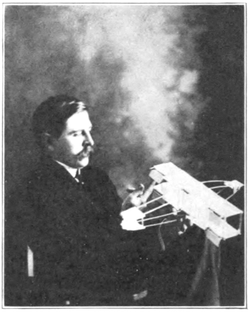
Author: Charles M. Miller
Release date: July 24, 2024 [eBook #74111]
Language: English
Original publication: Peoria: The Manual Arts Press, 1914
Credits: Carol Brown, Chris Curnow and the Online Distributed Proofreading Team at https://www.pgdp.net (This file was produced from images generously made available by The Internet Archive)
Transcriber’s Note:
In Memory of
Chris Curnow
(1937-2023)
the Project Manager at Distributed Proofreaders
who selected this book,
and more than 2200 others,
to be preserved as free digital transcriptions
by Project Gutenberg.
AND KITE TOURNAMENTS
Assistant Supervisor of Manual Training
Los Angeles, California
The Manual Arts Press
Peoria, Illinois
COPYRIGHT,
Charles M. Miller,
1914.
[Pg 5]
Perhaps the one word that best expresses the trend of education at the present time is the word life-likeness. The trend is toward more and more life-likeness in organization and methods. The effort toward diversification which has resulted in putting manual training into courses of study, in multiplying courses in high schools, in providing ungraded and other special rooms in elementary schools, in breaking grades up into groups for teaching and promotions, in keeping playgrounds and shops open afternoons and Saturdays, in opening the school buildings evenings for social centers or socialized evening schools,—which has resulted in all these changes and others that might be mentioned,—is simply an effort to make the schools like life. The theory behind this is that if a school is like life, children will like school for the same reason that they like life, and the theory is sound. Before these changes were introduced, our public schools were a composite structure, made up nearly altogether of two elements, neither of which was in any degree life-like. These two elements were the medieval monastery, for order, and the 19th century factory, for process.
Kite-making in connection with schools is in line with this trend toward life-likeness. As the ideas and plans contained in this book have been worked out and carried into execution in the schools of Los Angeles by the author, they have demonstrated a wonderful socializing power. By recognizing kite-season in the schools and carrying the discussion of it into the shop and classrooms, ending with a great kite-tournament each year, not only have very many boys been reached who would not have responded to other influences, but the whole community has been stirred to sympathetic interest in the schools. This is the kind of influence which causes children to feel that school is life, and therefore makes tremendously for wholesome education. If the ideas and plans of the author can be carried out elsewhere as they have been in Los Angeles for several years, they must prove a help to the cause of education.
M. C. Bettinger,
Assistant Superintendent of Schools.
[Pg 7]
When we started kite work in the Los Angeles City Schools, we little thought that so great an opportunity for awakening latent power in a certain class of boys was being initiated, nor did we dream of any such kite tournaments as have been developed during the past six years. Starting with half a dozen plans, sent out on mimeographed sheets to the various schools from time to time during the spring of 1907, the number of kinds and designs have increased to a hundred or more. Other cities desiring information regarding the work, a reprint was published and has been in such demand that it was thought advisable to write a more comprehensive text on the subject. Many of the former designs have been included, but none but what should be put in more permanent form, and most of these have been redrawn for the new work. The plans are not complete in every detail, something being left for the boy to work out, but there is enough in the suggestions so that by reasonable planning, most of the forms can be made by the average boy and still something will be left for the expert.
The greatest number of kites will be made by fifth and sixth year boys, but the spirit holds over into seventh and eighth for the larger and more complex forms, and even into the high school with model aeroplanes, etc.
It is the hope of the writer that this little book may be instrumental in giving our boys and girls suggestions for many happy hours in the construction and flying of kites, and that it may also serve a good purpose to teacher and pupil in reaching a common ground, and that it will help some mother in furnishing a good healthy pastime sport for boys who sometimes try the limit of one’s patience for the lack of something to do. It is a home construction work largely, and it has succeeded oftimes much better than was anticipated, for whole families have become interested in the development of OUR boy’s kite. Mother generally is interested first, while father looks with disfavor on so much time being spent on a kite; but before it flies, father gets very enthusiastic, suggests here and there, and furnishes material for string,[Pg 8] etc., with pleasure, and they all go to the tournament to see Jack win a first prize. This is one case, there are others.
I believe there is need for such books, and this subject is without such a text, therefore, this little treatise.
Charles M. Miller,
November 5, 1912.
Los Angeles, California.
[Pg 9]
| CHAPTER | PAGE | |
| Introduction | 5 | |
| Preface | 7 | |
| I. | General Kite Construction | 11 |
| II. | Kite Accessories | 16 |
| III. | Kinds of Kites | 20 |
| IV. | Plain Surface Kites | 23 |
| V. | Box-Kites | 39 |
| VI. | Combined Kites | 48 |
| VII. | Decoration of Kites | 61 |
| VIII. | Messengers | 69 |
| IX. | Moving Devices | 75 |
| X. | Suspended Figures and Appliances | 82 |
| XI. | Balloons and Parachutes | 92 |
| XII. | Reels | 97 |
| XIII. | Aeroplane Models | 103 |
| XIV. | Gliders | 108 |
| XV. | Model Aeroplanes | 112 |
| XVI. | Propellers, Motors, Gears, and Winding Devices | 121 |
| XVII. | Tournaments | 127 |
| XVIII. | Tournaments, Continued | 134 |
| XIX. | Conclusion | 140 |
| XX. | Bibliography | 142 |
The kite is usually made of a framework of wood, is lashed together with cord, strung with cord according to design, and finally is covered with paper; but in each case some other material might be substituted.
The drawings in this book have the framework represented by full lines and the string by slant dotted lines. The framework must be kept light and strong. It is usually made of wood, the pieces varying in number from two in the plain tailless, to sixteen in a good box-kite, and to a great many in a large tetrahedral kite.
The soft tough woods are better than the hard, heavy woods. Spruce is considered the most satisfactory, but yellow pine, basswood, and even white cedar will do. For a three foot kite, the California redwood shake is very satisfactory. It is a kind of long shingle of uniform thickness thruout, is six inches wide and three feet long. The shake is split into strips about 7/16” or ½” wide, and bends sufficiently for the bow. Some box factories will rip out spruce sticks in 25c. bundles for boys at about one penny each. Some good sizes are 3/16” × ⅜” × 3’, ¼” × ½” × 4’ and ⅜” × ¾” × 5’. These should be straight grained and well seasoned.
Sticks should be uniform in weight and bending qualities. Where sticks are to be centered, careful measurements must be made, then by balancing over a knife-blade the difference in weight can be detected and the heavy end reduced by whittling off some. Some try to find center by balancing, but this is very inaccurate; a string may be used for measuring.
Aluminum tubing is used, especially for parts of model aeroplanes, but it is not available in many places. Some make frames of paper, but they are more for curiosity than utility. For large frames bamboo is excellent, but requires a different fastening of joints than sawn out material, Fig. 1. Split bamboo is excellent for curved outlines and for light framework of butterflies and bird kites, and for Japanese,[Pg 12] Korean and Chinese kites. Wire can be used for frames of small kites.
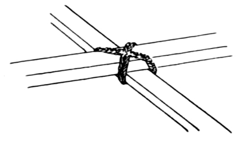
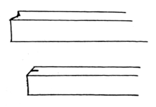
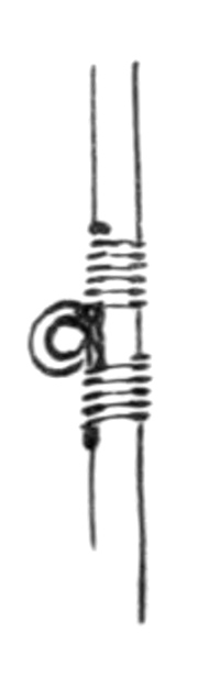
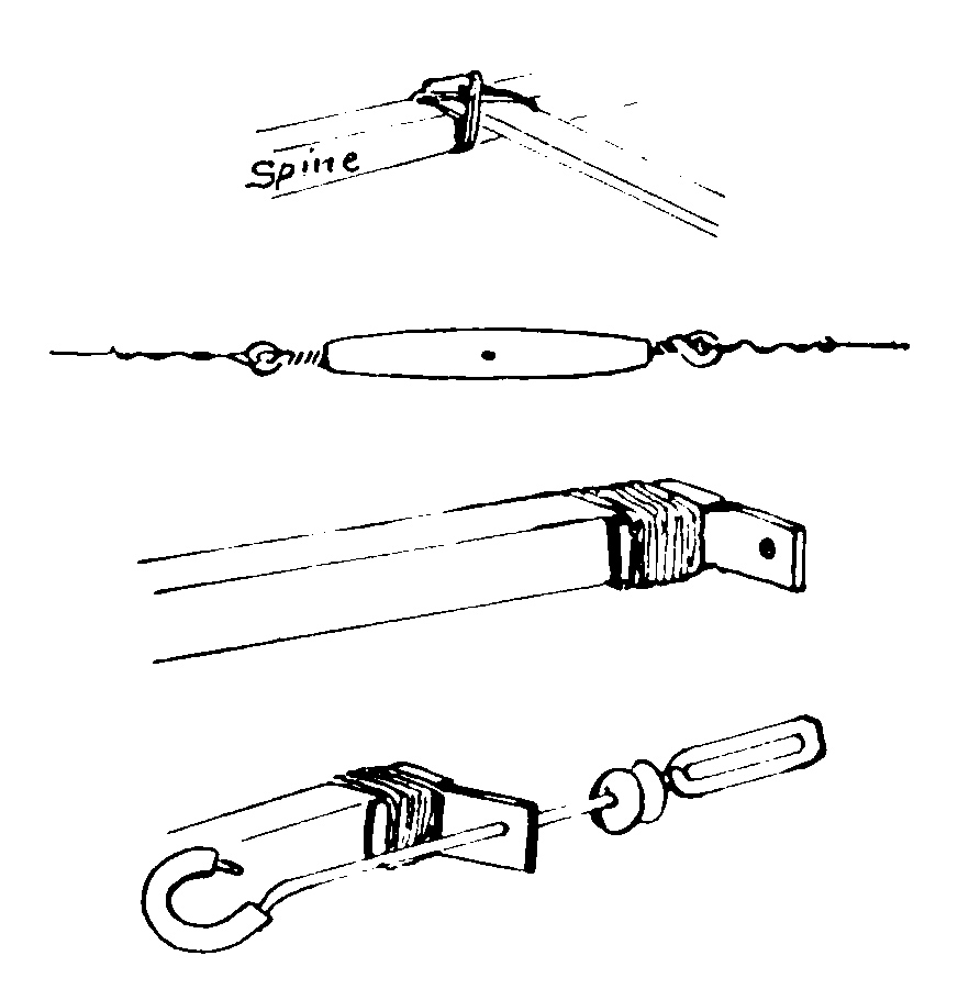
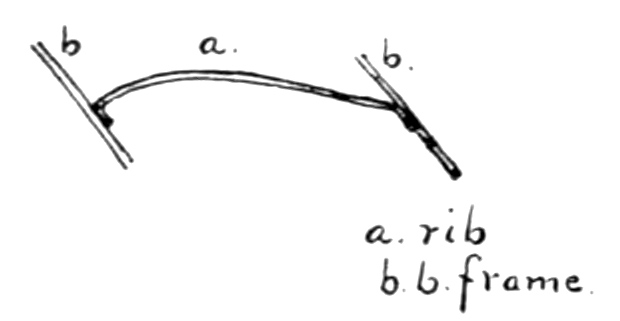
Lashing. When two sticks are to be fastened together, instead of nailing with a small brad, they should be lashed. First wind diagonally around both sticks in both directions, Fig. 2; then wind between sticks around the other windings. This draws all the cord up tight, Fig. 3. Coat over with glue or shellac.
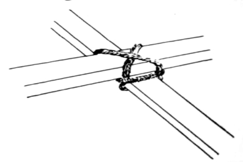
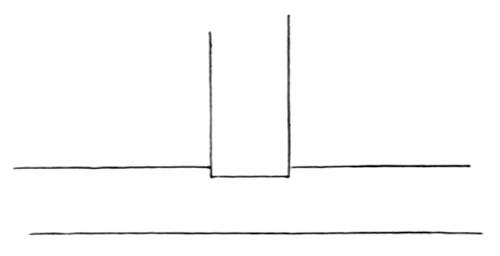
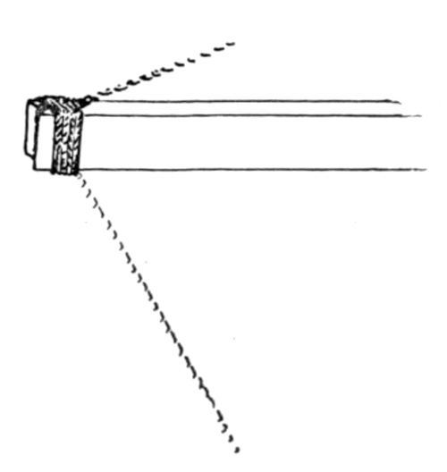
Large box-kite frames with sawn out material should have the upright posts let into the long horizontal pieces a little, Fig. 4. If a brace is notched at the end to fit over another piece, Fig. 5, and is liable to split out, it can be wound just back of the notch with thread, Fig. 6, and coated with shellac. All windings should be neatly done without criss-cross windings as in Fig. 7. Which do you like best Fig. 6 or Fig. 7?
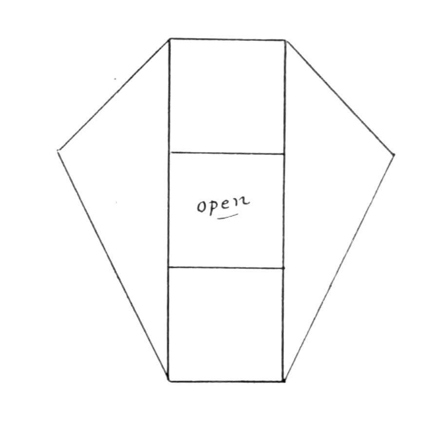
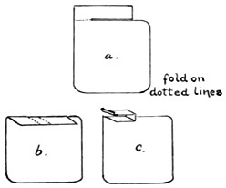
Collapsible Frames. Folding frames can be made for most kites. Large tailless kites have either a removable spine or bow, the square box-kite has braces that spring into shallow notches, and the triangular box and house kite combination can be rolled by having a removable cross-stick. It is a great advantage to have folding kites.
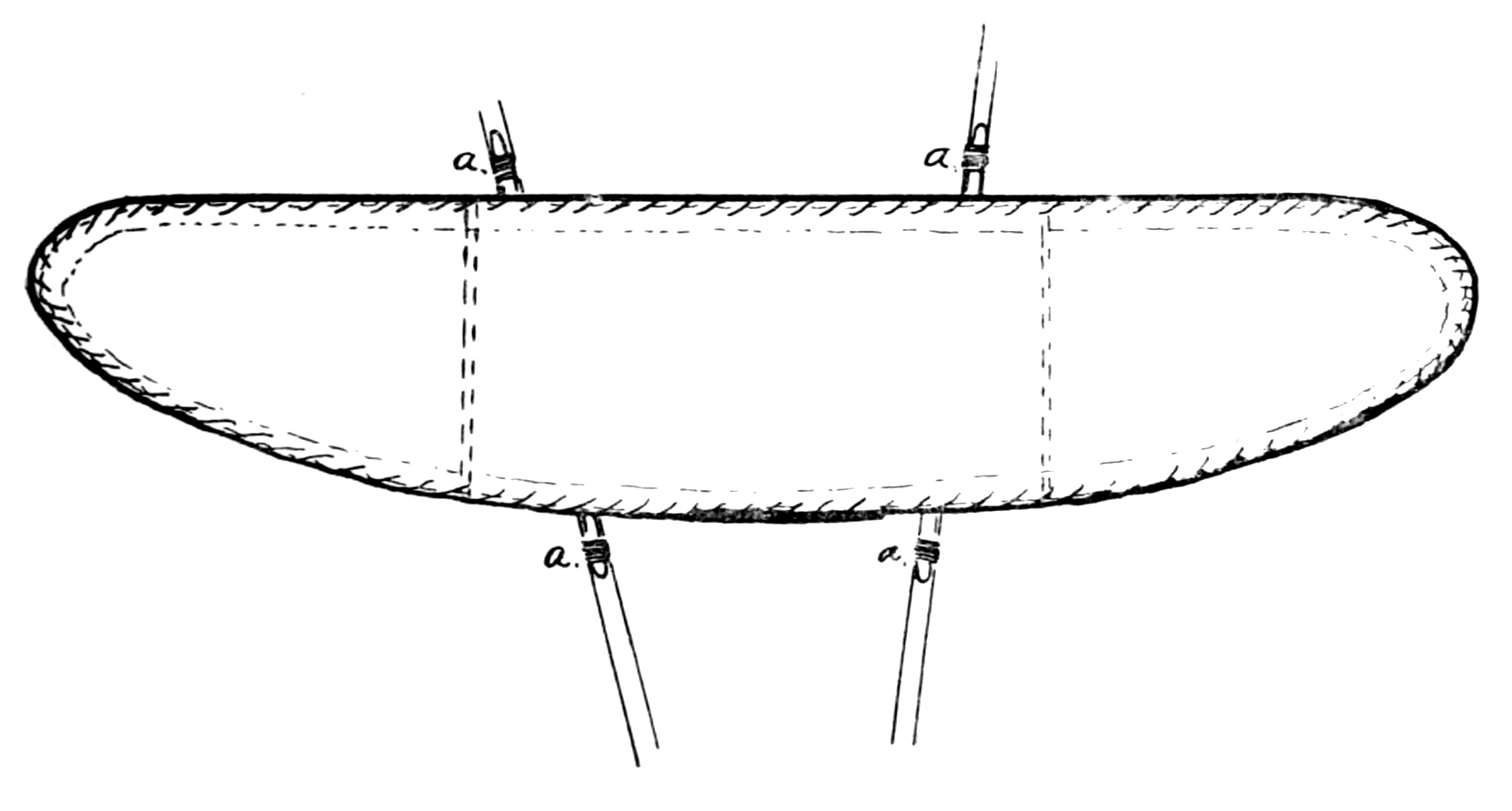
[Pg 13] Stringing. Symmetry is so necessary in the making of a good kite, that the stringing becomes an important factor; for if two opposite sides are made unequal, there will be more pressure on one side of center than the other, the kite will be pulling off to one side or darting down and perhaps will refuse to fly at all. A small hard twisted cotton cord is good for stringing as it does not stretch.
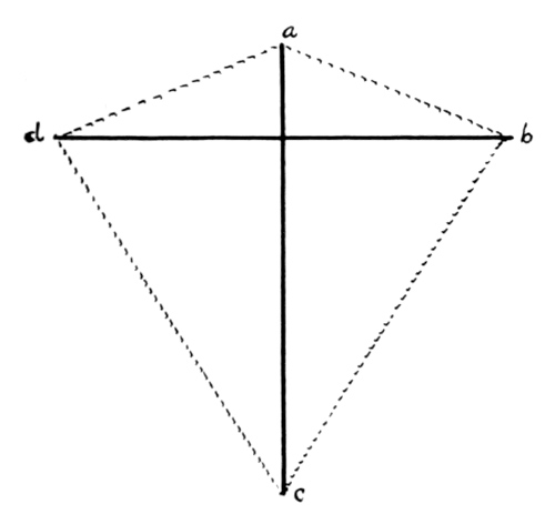
On kites where the string passes around the entire frame, Fig. 8, it is best to fasten at the end of one stick only, as at a, then pass in the notches of the ends of the other sticks at b, c, d, and tie again at a. We must assume that the horizontal stick in Fig. 8 has been measured accurately for center as that is a part of the framing process. The sticks can be notched with a knife, Fig. 9, or a saw-cut can be made in the end, Fig. 10. The latter is less liable to split out, but the first is more convenient, for every boy is likely to have a knife or can borrow one.
After the string is secured around the entire figure, adjustment between points is made. If a tailless kite is being strung up, the two upper portions are shifted until the right and left sides are equal. The ends are then[Pg 14] wound with another cord, Fig. 11, to prevent slipping. The two lower sides are then spaced and the lower end of the spine is secured in the same way. Some may think it a waste of time to measure the lower strings after the upper ones have been adjusted, but very often there is quite a little difference, due to a springing of the spine. A six pointed star kite would have six, instead of four spaces to even up. Some stringing is used for inside designs, and some is used for strengthening frame.
Covering. Probably more tissue paper is used in covering kites than any other material. There are a number of kinds of tissue papers, but the cheapest, because it is the cheapest, is used most. These cheap tissue papers are now found in all shades and tints of colors.
The French tissues are more durable, and as a rule, more brilliant in color. A kite covered with this paper can be used from time to time without being disabled.
The Chinese tissue paper is the strongest of all tissues in one direction, and should be used so as to bring the length way of the paper in the direction of greatest strain. This paper only comes in a cream color, but is very satisfactory where strength and hand color work are desired. In Los Angeles we get two sheets for five cents, and the size is 22” × 23”. There are some wrapping papers that are pliable and strong enough to be used, especially on box-kites, but only a few of these are of much service on plain surface kites. The tight covering on a box kite is an advantage. Some boys use a paper that is commonly known as a butter paper, and others find orange wrapping paper serviceable.
Of the cloth coverings, cambric is the most popular. The sizing is sufficient to keep the covering in shape during construction, it is light in weight, comes in variety of good colors and is cheap. When cloth is used on plain surface kites, care must be observed that the goods are not used on the bias, as the unequal stretching would unbalance the poise of the kite. Silk is excellent, but ——!! it isn’t used much by boys.
[Pg 15] Most coverings are turned over the outer strings, and are pasted or sewn down. In representative figure kites, the edge of the paper is sometimes left free, while the string is made fast by extra strips of paper pasted fast over the string and to the back of the cover, Fig. 12, thus leaving the edges to flutter in the breeze. Some large kites can be covered with paper, if a network of string is used at the back to give support to the covering.
Tailless, and some other kites require loose coverings, this looseness should be planned for in a systematic manner. If the cover of a 3-foot kite is placed on a table or the floor with the frame laid on top, the edge of the cover may be cut one inch or one and one-half inches to the outside of the string. Instead of turning in this whole amount, only turn in one-half inch of the outer edge. This leaves plenty of looseness for bagging of cover, and is regular.
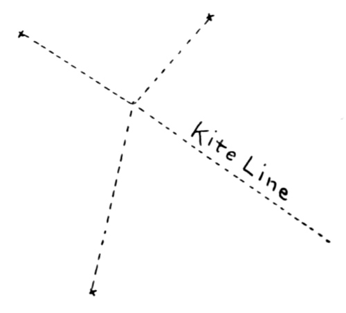
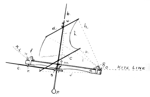
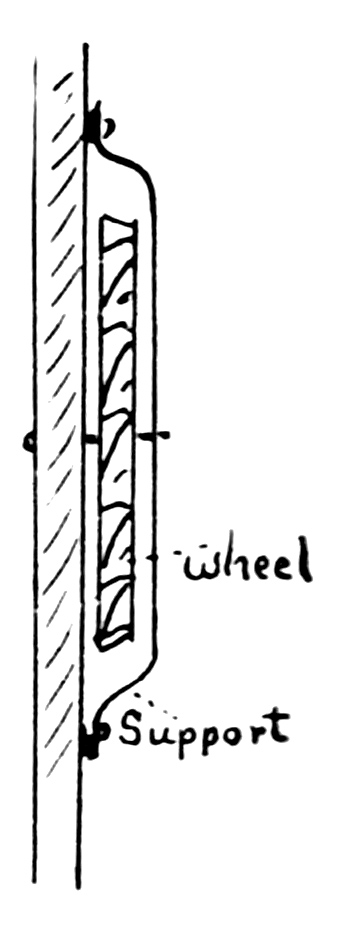
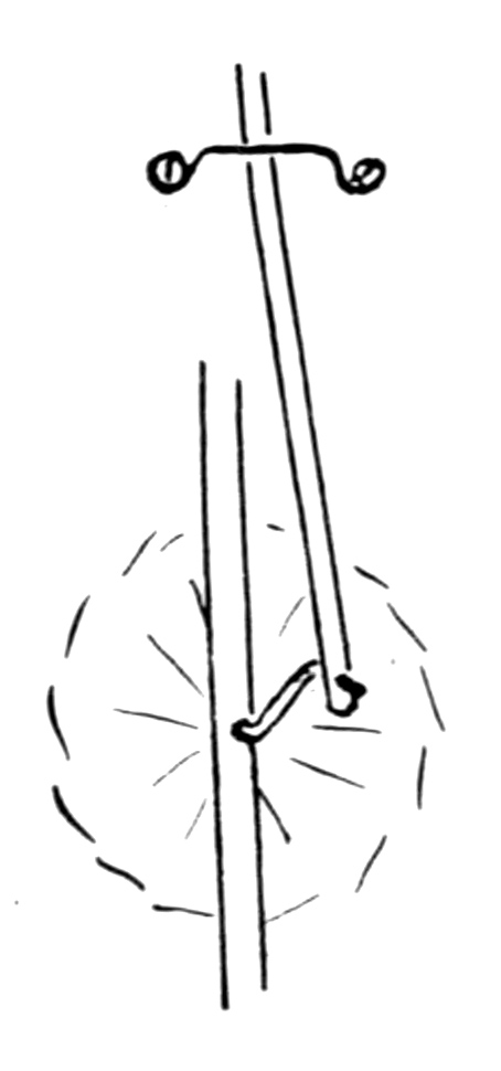
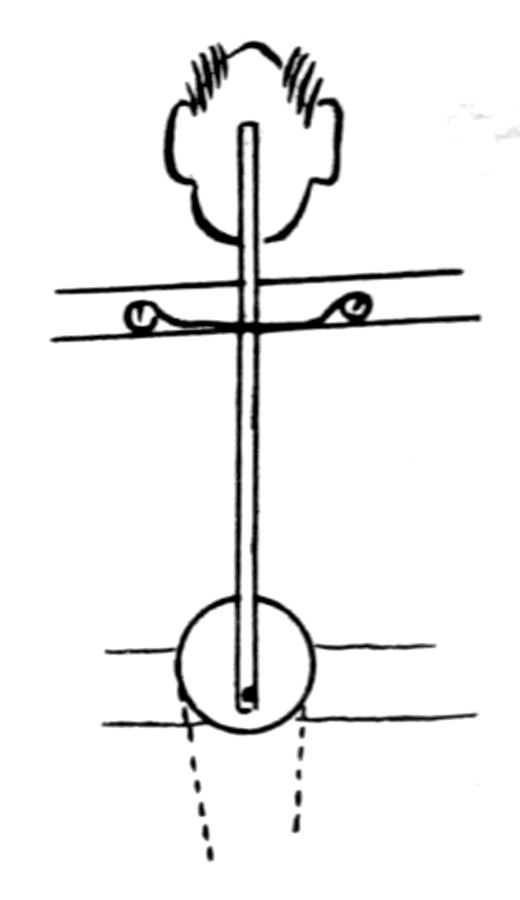
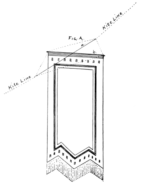
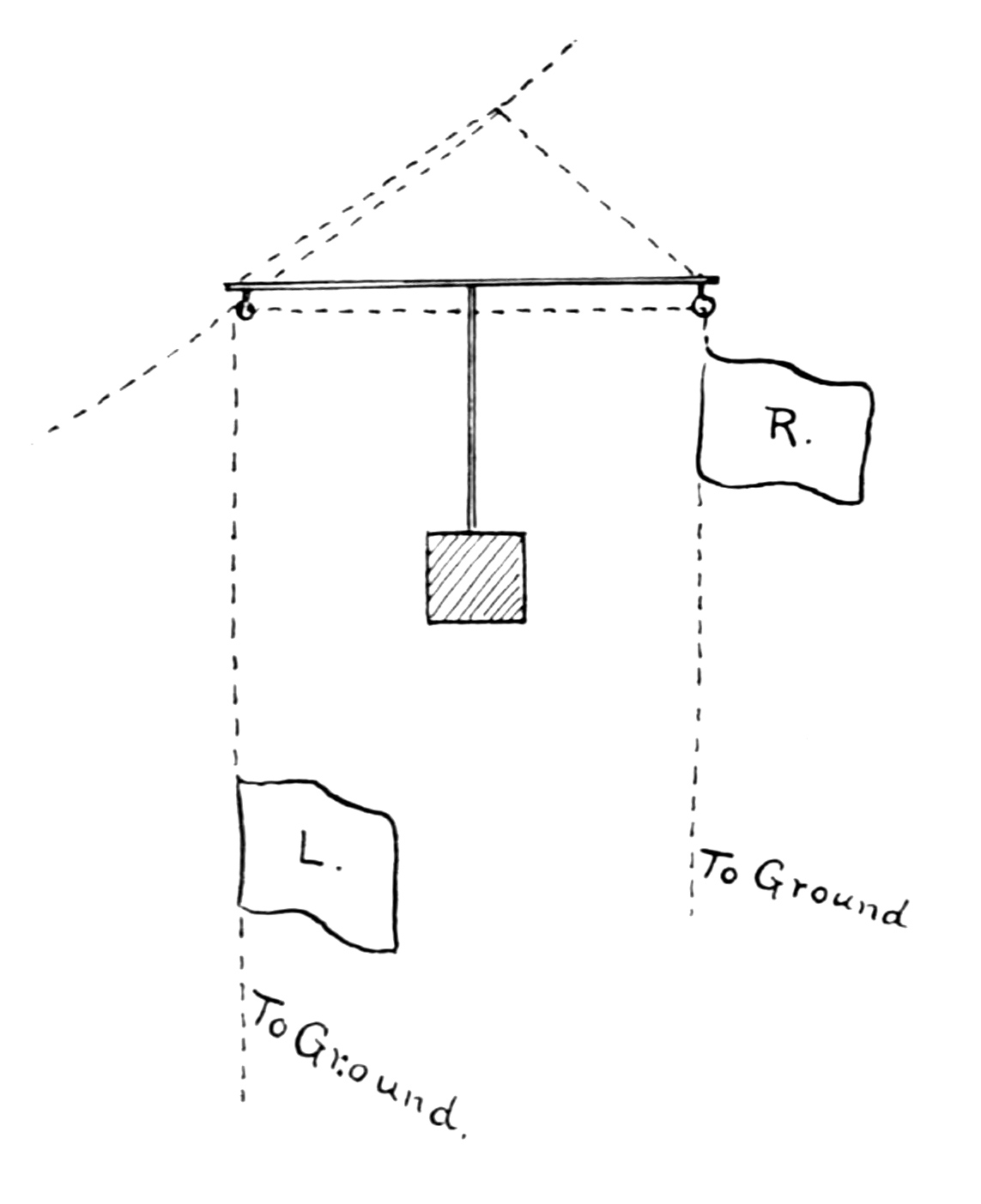
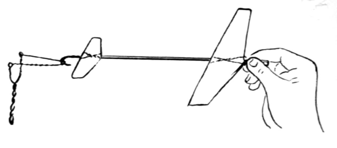
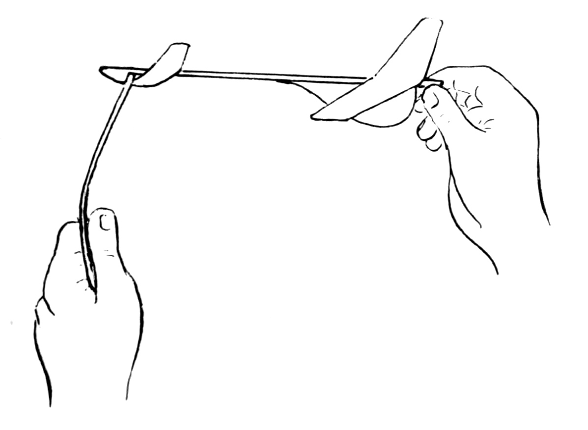
The Bridle. The kite is not supposed to be finished until the bridle (or belly band) is attached. Nearly all kites require a bridle, a very few have the kite line tied directly to some one point of the framework. The bridle is a very important part of the kite equipment, as the kite is dependent on it for the proper distribution of pull by the kite line, it also gives the inclination of the exposed surface to the breeze. The inclination is varied slightly for various purposes, such as high flying, strong pulling, steady flying, etc. To make the kite fly directly over head, the kite line is attached above the normal point, and to make it fly low, the attachment should be below normal. If the single line can be attached to the framework so as to give this inclination, no bridle is needed but it is usually difficult to locate the right point.
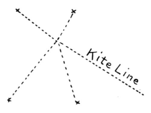
Many kites need attachment of bridle in but two places, while others require three, some four, and some are benefited by the use of[Pg 17] many strings to the bridle, but the last may be used for strengthening the framework of the kite more than for general poise. The Chinese say there should never be more than three strings to the bridle, while the Japanese use many.
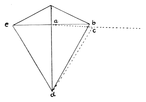
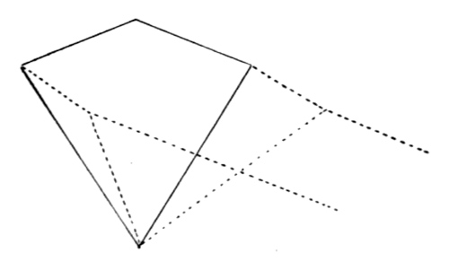
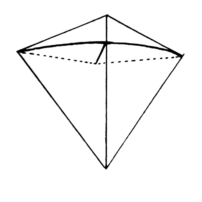
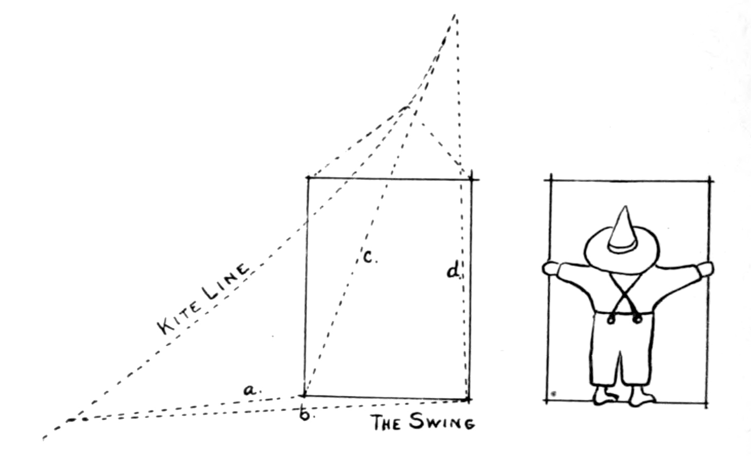
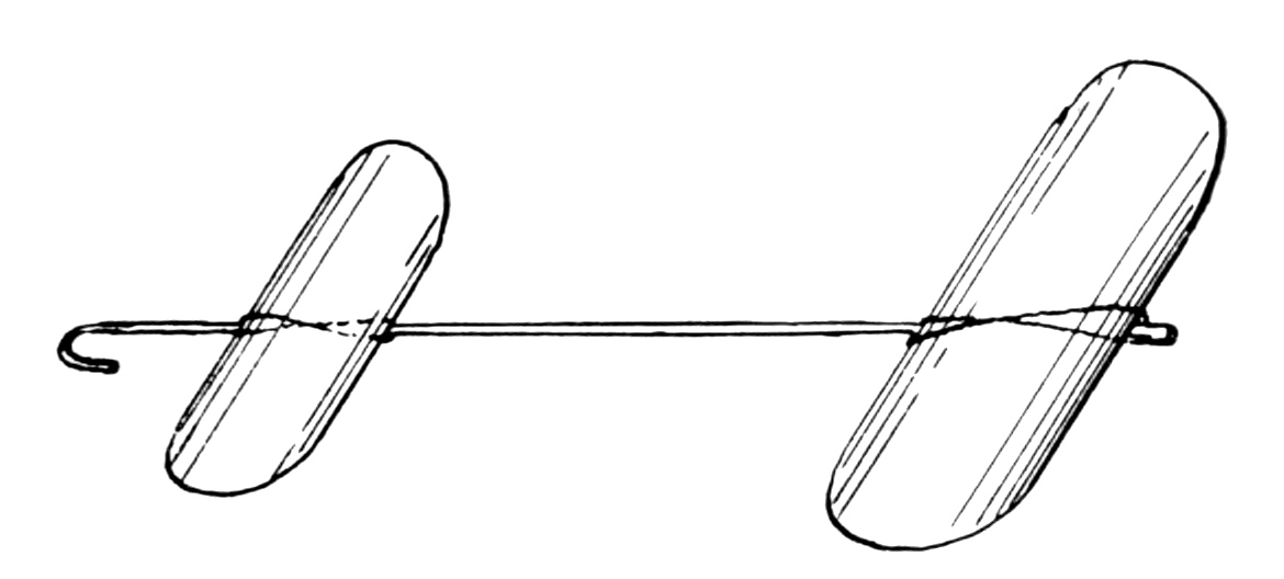
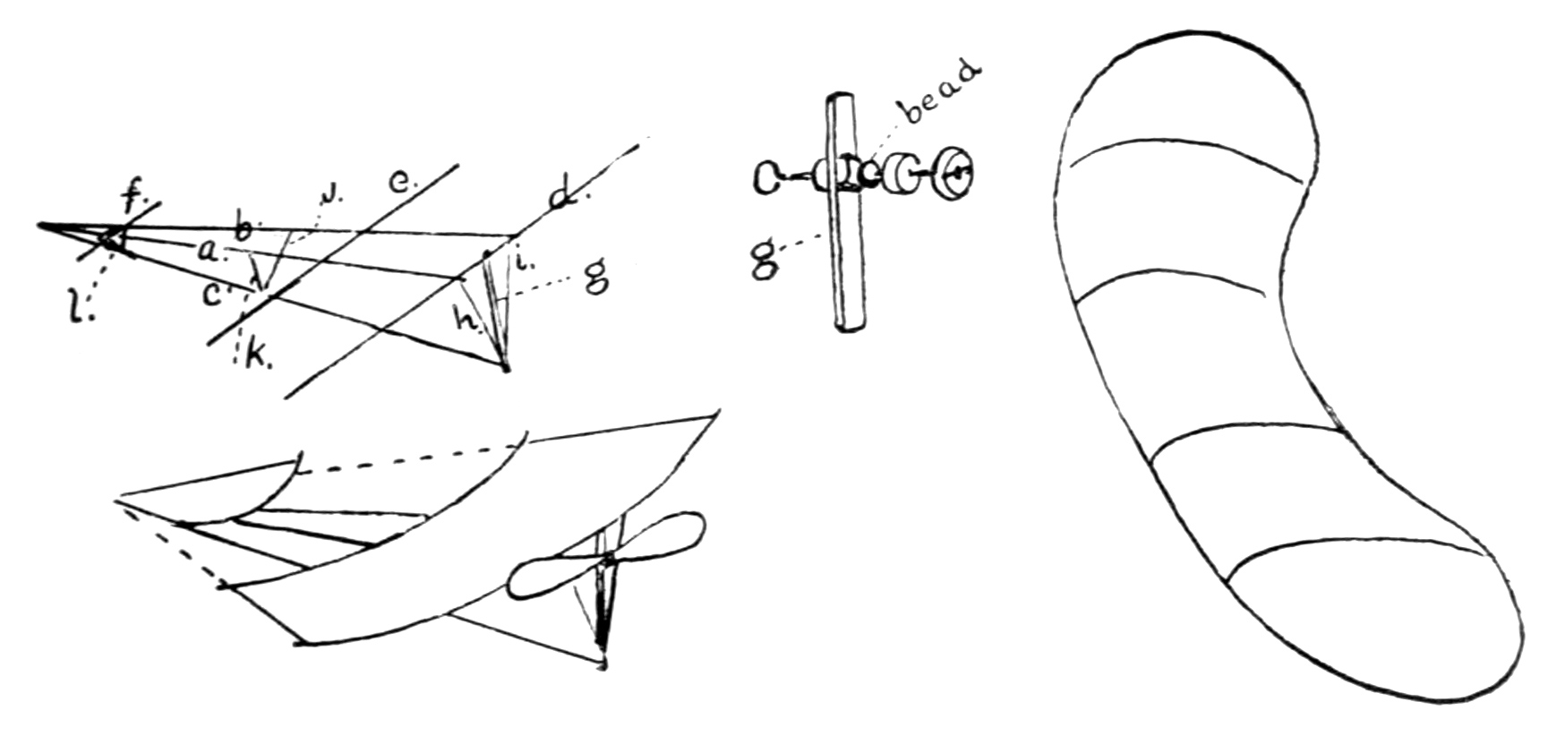
The tailless kite may have the bridle attached at the bottom and top of the spine (the vertical stick of the frame) or the bottom and at the crossing of bow and spine. In either case the bridle must be long enough so that when it is drawn over to the side of the kite, the loop will just reach the outer points of the bow, Fig. 13; ac should be the same length as ab, and cd the same length as bd. The normal point of attachment of kite line is at c, the point that just reaches b or e when drawn to the side. Some bird kites have a similar bridle but much shorter between attachments. More of the form kites have three and four strings to the bridle. The three string bridle is usually two strings above and a longer one below, Fig. 14. The four string bridle has two short uppers and two long lowers, Fig. 15. For the poly string bridle, see Fig. 16. Some have advocated an elastic bridle but the writer has never found it of any great advantage.
A double bridle with a kite line to each, makes a dirigible kite possible, which may be useful in a number of ways and which can give much amusement in kite antics that is not possible with a single kite line. A double bridle is illustrated in Fig. 17. Such a kite can be driven at will. The kite becomes a sail and can be pulled to right and left, in circles and various contortions, out of the ordinary.
Kite Lines. A three or four ply cotton wrapping string is used more than any other and is very satisfactory for three-foot kites and smaller. The hard twisted cotton seine twine comes from six to over[Pg 18] a hundred ply, and is excellent for kite lines. It is strong and does not burn the hands, nor kink as much as hemp twine.
For high flying or racing work, a light strong cord is necessary. A small kite can carry up a great amount of silk or linen thread but one should have a reel and gloves to handle it. Shoemakers thread and upholstering twine are also used. Some think that waxing a string makes it stronger, but by actual tests before and after waxing, there was no appreciable difference in the amount of endurance of strain before breaking. Waxing does preserve the string and prevents fraying and untwisting.
When kites are put up in tandem, the string need only be as strong for the first kite as is ordinarily used for one of its size, but as other kites are added the size of the cord must be increased. This grading of the string, greatly reduces the total weight and cost of the kite line.
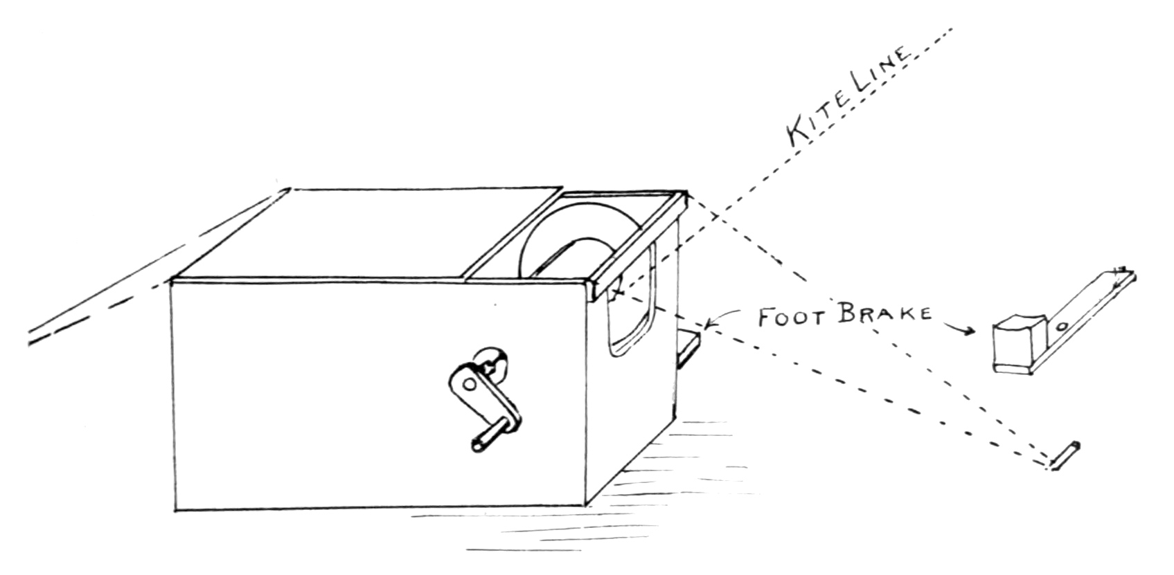
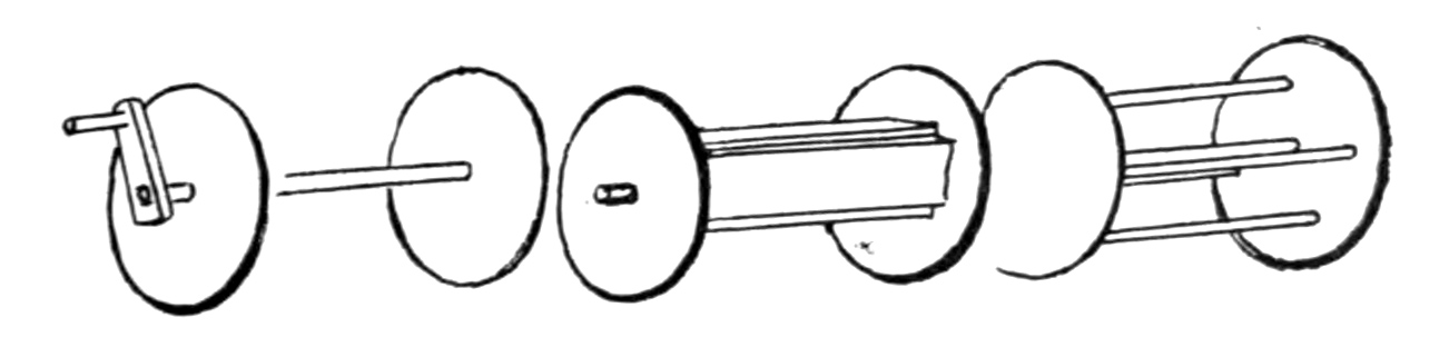
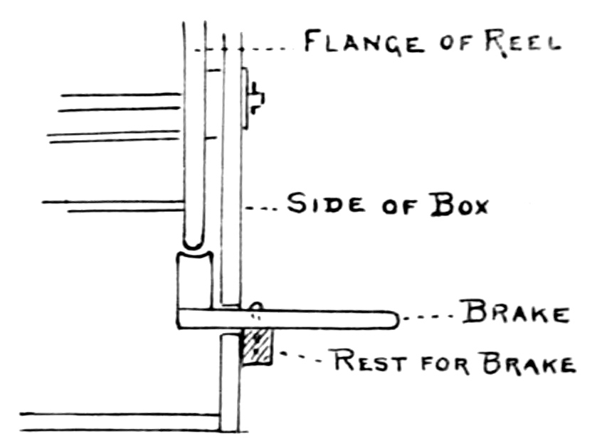
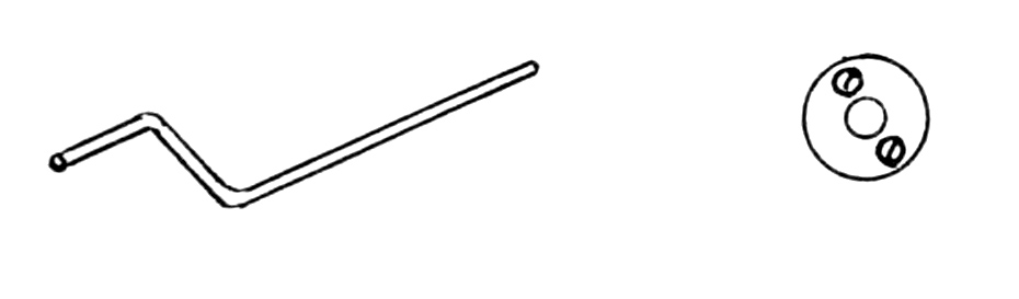
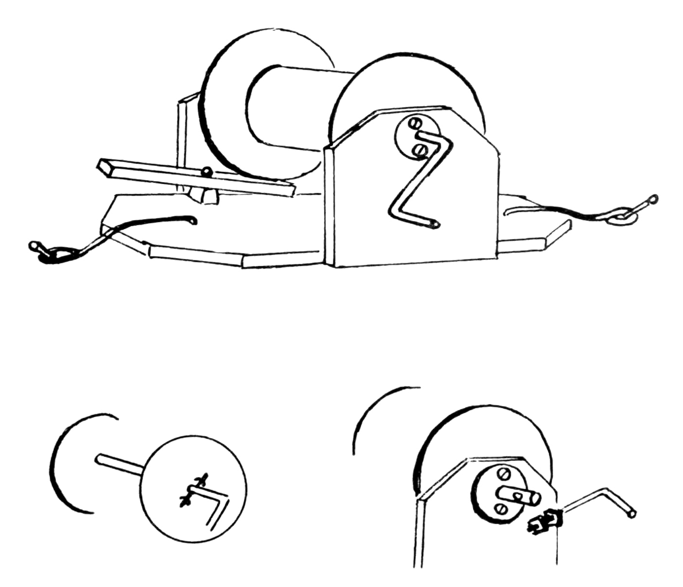
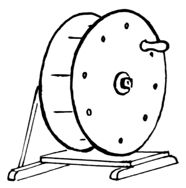
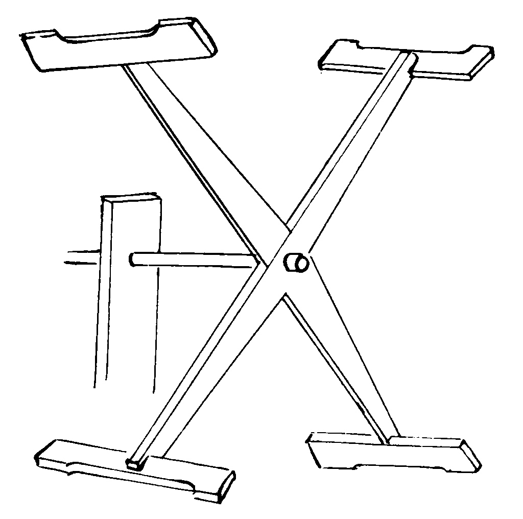
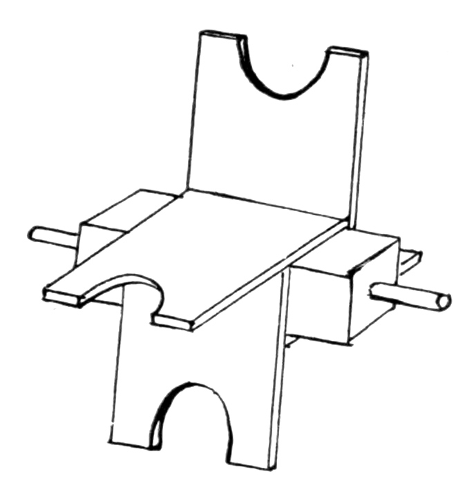
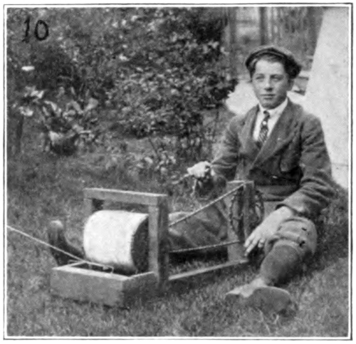
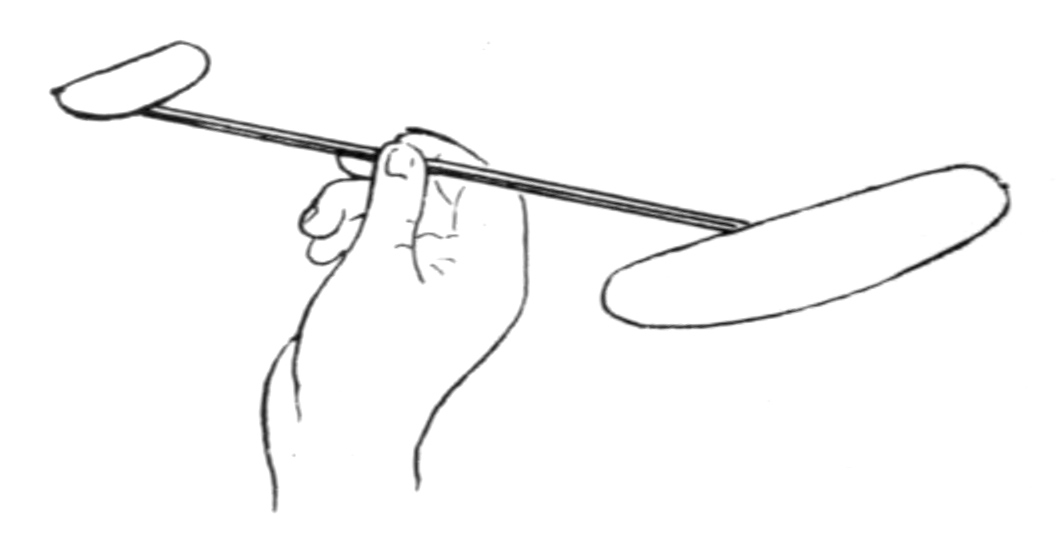
Reels. You can fish without a reel and you can fly a kite without one, but the reel is a great convenience and an absolute necessity at times for both. The reel in brief is a large spool with flanges on both ends, a central axle fixed to the spool, a frame for supporting the axle, a guide for the string to prevent its running off the reel, and a brake to prevent too rapid unwinding when letting out the string. A reel can be made without a crank, by having the axle supported at one end only, and a knob handle fastened to the outer face of the reel for winding purposes. For further directions, see chapter on Reels.
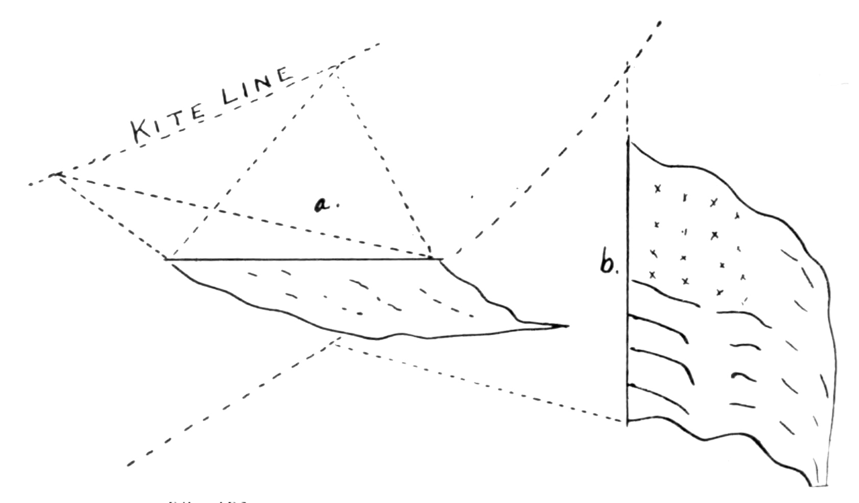
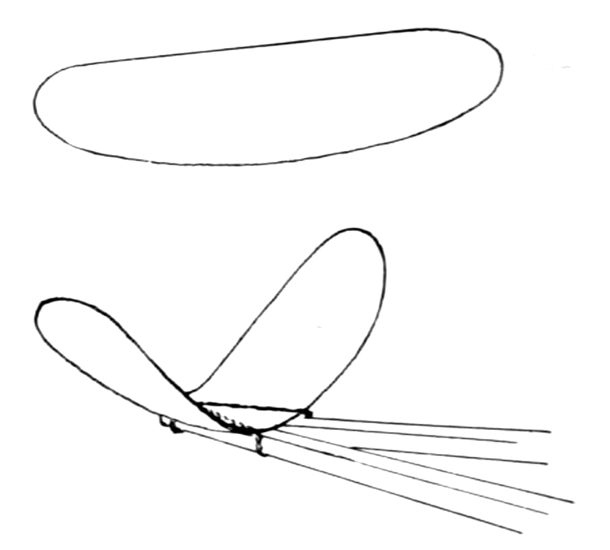
Tails. A tail and other balancers are used to give poise to an otherwise unsteady kite. When a kite is constructed in such a way as to present a broad flat surface to the breeze, it will sway and dive and no matter how carefully you attach your bridle it cannot be supported in the air.
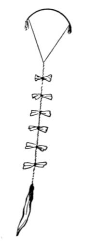
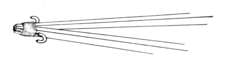
For kites that represent irregular forms, there must also be a special balancer. The tail is usually resorted to in such cases. The tail is more than a weight. A foxy kite refuses to come to terms by the addition of a thread and lead or other weight. The weight drops so quickly to its plumb[Pg 19] line that the kite has not come to poise, and makes another pitch in some other direction. The value of the tail depends not so much on weight as on its pulling capacity while being drawn thru the air. The tail, usually consisting of a string with a number of pieces of paper folded and tied thereon, Fig. 18, and with cloth streamers at the end for weight, exerts considerable pull for long enough time to give steadiness to the kite. A kite must have poise in the air just as we balance a board on the end of a finger—if the finger is not centrally located, the board will fall to the left or right, front or back; so with the kite, if the pressure of the air is not centrally located it will glide to left or right, or pitch forward or tumble backwards. The tail helps most in remedying the two latter troubles. Almost any light surface can be supported in the air by proper attachment of bridle and tail. The Japanese use two or more tails on their square kites consisting usually of long cotton ropes with large tassels on the end. These look very beautiful trailing out in long graceful parallel lines.
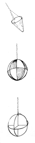
Another form of air resistance found serviceable, is hollow cones or funnel shaped devices of light cardboard attached by cords to the kite in place of tails, Fig. 19.
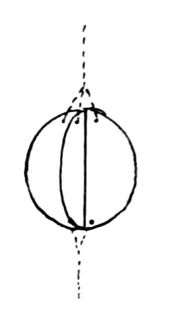
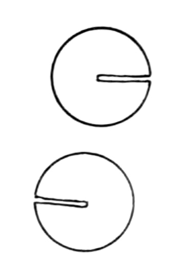
A Chinese boy had a colored paper ball about 8” in diameter attached by a string to one of the kites last year, Fig. 20. Another form is the intersected cardboard discs, Fig. 21. Other forms can be used.
Christmas and other paper rope used for decoration purposes could be used to advantage for tails of kites. They will catch the breeze and can be festooned into pretty designs but will need cord supports to give strength.
Don’t throw away a kite because it has to have a tail. The tail is sometimes the most beautiful part.
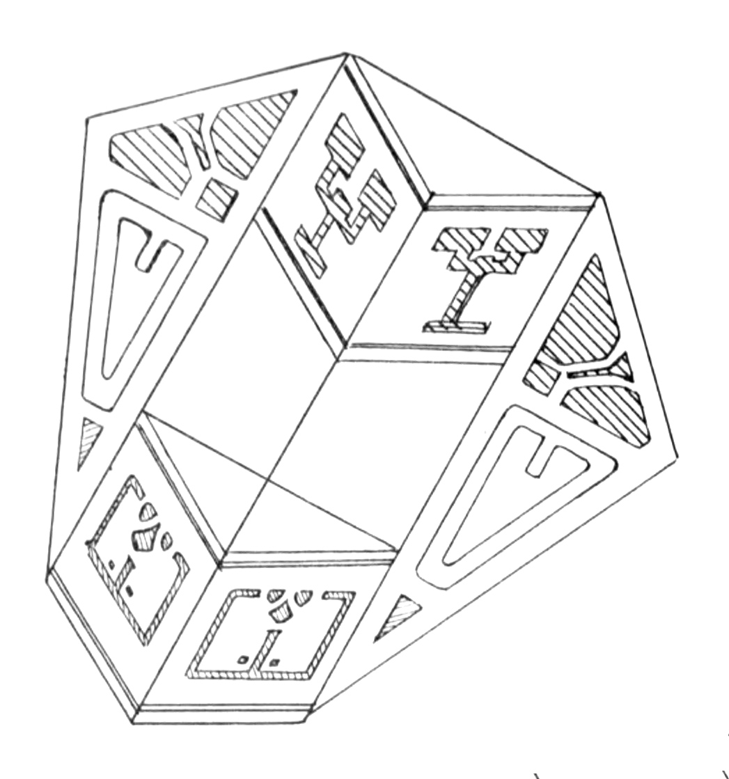
Kites are so numerous in kinds and design nowadays that, in order to get at any kind of intelligent discussion of them, it will be necessary to segregate them into classes and varieties as the scientist does in his investigations of nature study. There is the great big subject of constructive sport called kite making. The name kite strikes joy to any live boy’s heart and it does him good too. But kite making is too big, so we will try running some cross-roads thru, thus dividing it into smaller groups.
A large number of kites can be classed together as having the same general make-up and we will call the first, Class A, Plain Surface Kites. These kites have one general surface without any built out parts, and can be subdivided into two divisions: 1. Geometric and regular forms, 2. Irregular and representative forms.
There are two divisions of the geometric and regular forms:
The two divisions of irregular forms are:
This brings the analysis for Class A down to variety which will be discussed in succeeding chapters.
Class B. Box-Kites, has six subdivisions:
Class C. Combined Kites. Box-kites may have additions of plain surfaces, or combinations of curved surfaces and plain ones, giving shapes that represent hollow forms of fish, animals, etc.
[Pg 21]
Class D. Kites in Series. These are made up of combined kites also, but the combinations are so different that they belong in a class by themselves.
The plain kites are the more numerous for several reasons. They are more easily constructed, take less time, use less material, fly in lighter breeze, and are usually more stable in air. The construction as a rule consists of two or three sticks as a framework with a covering stretched over it so as to form a simple plane that is exposed to the breeze. Of course, there are tricks in making the plain kites, but almost any of them can be made to fly by either warping the surface or attaching a tail.
Box-kites require considerable time and are more difficult in construction. They are a built up framework with cloth or strong paper coverings. The frames must be kept light and strong, and a process of trussing is necessary to accomplish this. The covering seldom covers the whole framework but usually is made in bands. The space enclosed by a band is called a cell. Most box-kites consist of a forward and rear cell, that is a band is found at each end around the framework, transversely to the length of the kite. Some of the most practical working kites are of the box-kite type. By working kite, I mean kites that are used for a purpose other than pleasure.
Some box-kites have extended wings of plain surfaces to gain more lifting power, or for poise, and the application of these appendages serves to explain the combination of kinds that form this group.
In the group “Kites in Series” we have kites of the same kind fastened rigidly together making one kite, called a compound kite, also kites fastened one after the other a few feet apart on one line and all started up at one time, and still another set of similar kites in which a number of kites are put up on individual strings, one at a time, for[Pg 22] perhaps 300 feet, and are then attached to the main kite line. Boys sometimes succeed in pulling up as high as forty kites on one line by this method. Another very interesting and beautiful series is the Chinese dragon kite type. In this a number of kites are harnessed together with about three cords running from head to tail.
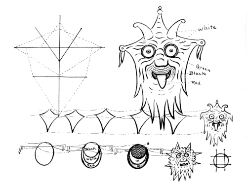
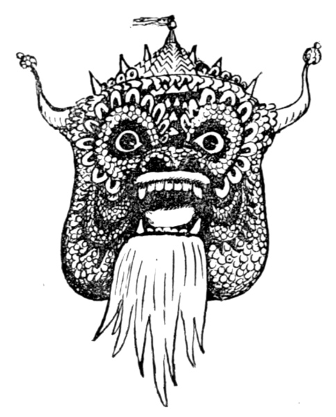
These various groups will receive more explicit directions in separate chapters as we proceed. So far in our analysis we have been dealing with kinds of kites as to construction. There will be a number of chapters on various other features of kite work and accessories, including, Kite Decoration, Messengers, etc. The Chinese and Japanese people have been making kites a great many years and have become very skilful workers and decorators. Their decorations seem to tend more toward the depicting of ugliness and fierceness instead of beauty and color harmony, altho many of the color combinations are very effective. The tendency toward fierceness can well be understood when we consider that it has a part in their religion, it being supposed that such ugly monsters helped to drive away the evil spirits.
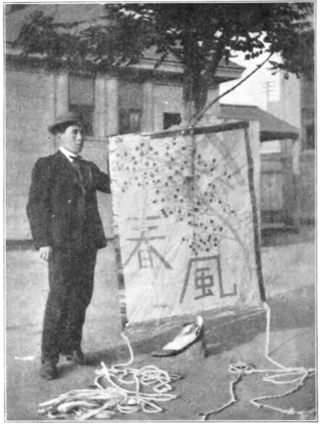
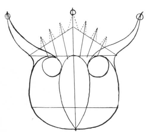
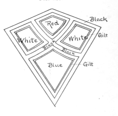
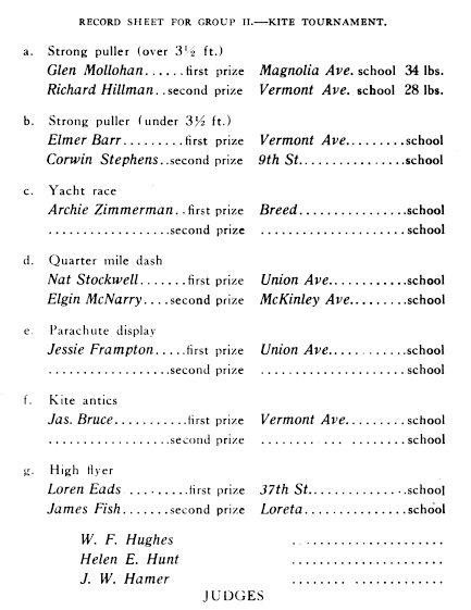
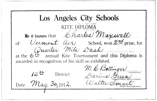
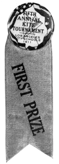
The large Japanese square kite, which is rectangular in shape instead of square, usually has a big head with plenty of the whites of the eyes and teeth showing. Some very fine specimens have been exhibited at our “Kite Tournaments”. They expend quite freely in making up their kites, use costly ornaments and considerable gilt and black. The gilt is usually very good that is used.
While the orientals have shown us some stunning effects in decoration, I believe that the future will show some results of color harmony and artistic spacing that will be much superior to theirs. We are busy as yet trying to master the kite craft from the constructive and flying side, but we are getting on, even on the decorative side as well.
We are now ready to discuss variety in the next chapter.
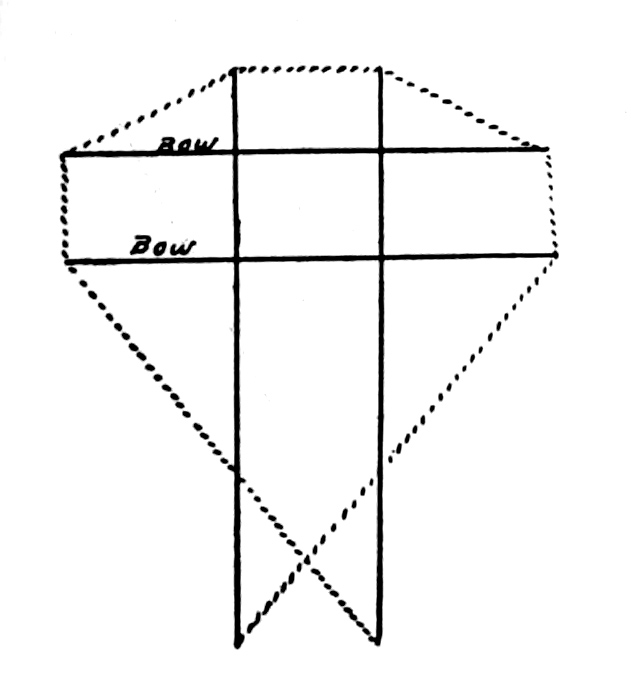
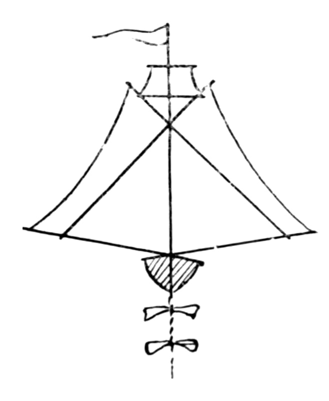
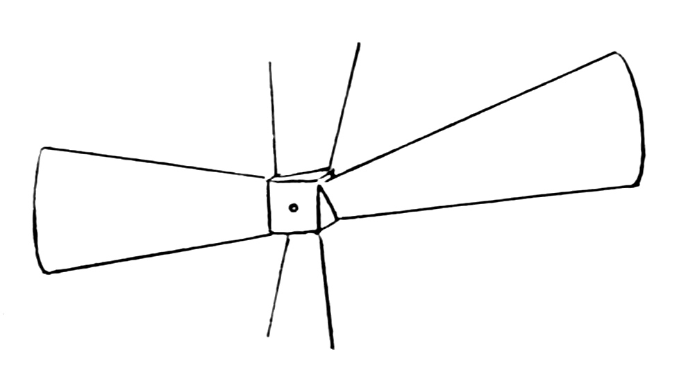
The tailless continues to be the most popular of all the kites. No matter how artistic, how representative, how curious, or how mechanical the new kites may be, the tailless is the first and last out every season. It flies in a very light breeze, and is so steady in the air. There are several kinds of tailless, but the two stick Eddy Kite seems to be the winner. These kites are made from five inches to thirty feet in height. This kite, Figs. 8 and 22, has two sticks of equal length, the vertical stick is called the spine, and should be straight, while the bow is placed about one-fifth the distance down from the top of the spine. This bow stick is bent backward by inserting a brace stick as shown by Fig. 23.[Pg 24] The advantage of a removable brace stick will be recognized when a person tries to carry several kites to a field at one time. If the brace stick is out, the kites lie flat and do not injure each other, so that twenty-five or more might be carried by one person, but if the kite is bowed, there may be great difficulty in carrying two or three. Most boys bow about three inches for a three-foot kite. See Chapter 1 for the stringing of this kite.
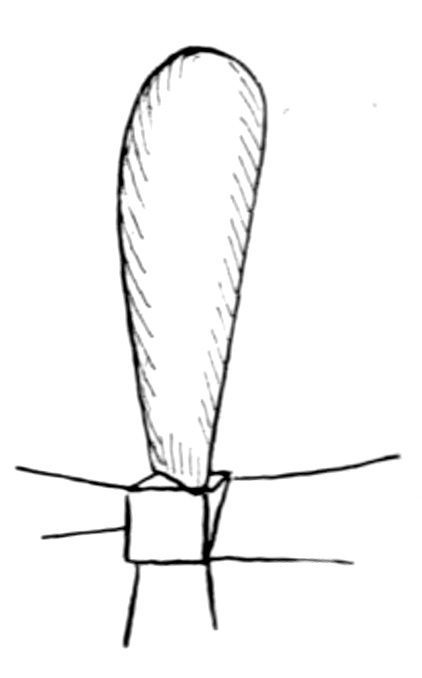
The tailless kites are nearly all constructed so as to have a keel projecting out to the front. In order that the keel may be of more service, the covering is not stretched tight, but is left loose. Perhaps an inch along each side would be allowed for bagging or pocketing. See Chapter I on covering. If the covering is drawn tight, the kite will dodge and will probably dive to destruction.
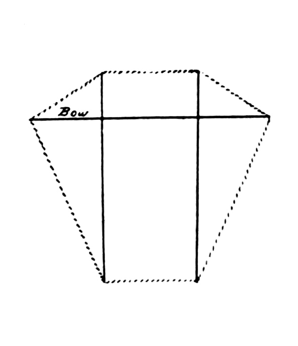
Now we can modify this type form of kite. We can use two spines and two bows, Fig. 24. In this kite the upper bow should be bent more[Pg 25] than the lower, and the bridle will be of more service if attached to the upper bow at two points about midway from spine to end of bow. The covering should not be quite so loose on this kite as on Fig. 22 but should not be tight. Another variation is given in Fig. 25, in which two spines are used and one bow. Sometimes the spines are crossed as shown in Fig. 26, the distance being much greater at the bottom than at the top between the ends of the spine sticks. A modification of the last two is shown in Fig. 27, in which a built out keel is shown. Two small braces project from the bottom of each spine with a third stick connecting their meeting place with the center of the bow stick.
Still one other combination is a form that can be used as a foundation for many outline shapes. It is shown in Fig. 28, and has two spines and two bows; but where much modification is made, a tail or other balancers must be used. A kite with a broken bow is like a bird[Pg 27] with a broken wing, but if broken in the center it can be redeemed for service by the addition of a cross-stick, as shown in Fig. 29. The broken part should be well lashed together. A kite could be successfully planned in this way from the beginning. It is possible to make a number of geometric or representative forms as tailless kites, but representative forms as a rule need tails.
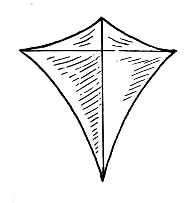
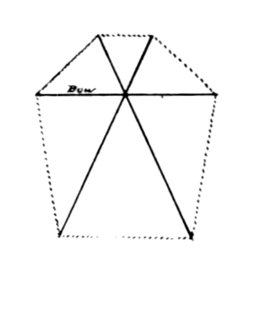
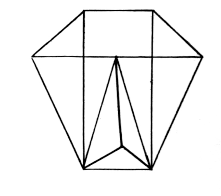
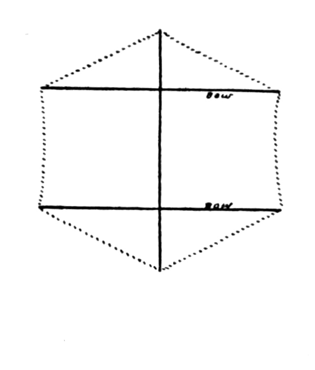
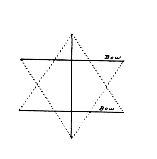
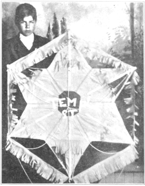
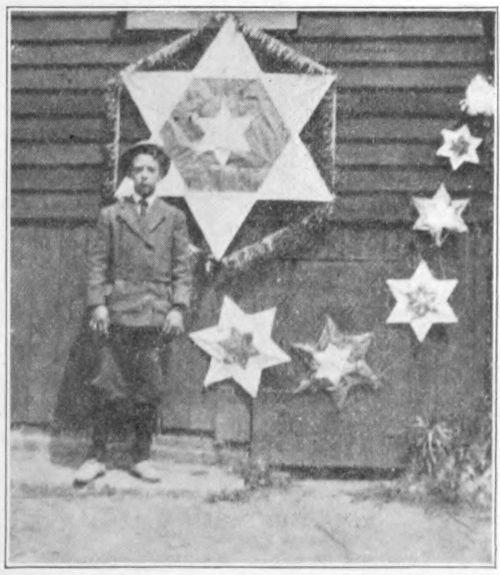
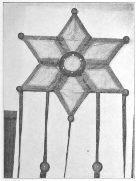
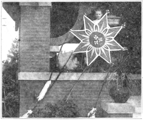
The shield, Fig. 30, is one of the tailless kites and the writer succeeded very well with a two bowed tailless in the shape of a six pointed star. See Fig. 32.
Perhaps the largest group in real variation is that in which kites with tails or other forms of balances are found. And first and foremost, comes our grandfathers’ old English bow kite, Fig. 18, having a bow that curves upward, but not backward, over the end of a single spine. Tassels were added at each side of the kite at the termination of each end of the bow, and a long tail of rolled papers tied to a string with a cloth hanging at the end was attached to the bottom of the spine.
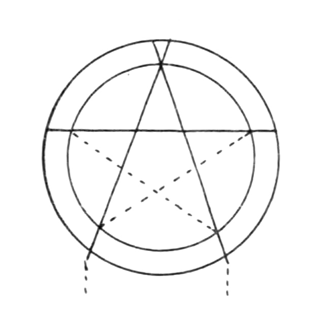
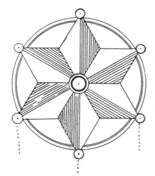
The great class of star kites, with varying numbers of points, and the geometric, hexagonal, octagonal, and other forms belong to this group. A three string bridle is most satisfactory for most of these forms. The two upper strings of bridle should be the same length but shorter than the lower string. The latter should be attached at a central point at the bottom. In case there is no stick to anchor to at the center of the bottom, four strings may be necessary or two longer ones may be used at the bottom and one shorter one at the top. However the bridle is attached, the shorter strings are always at the top, and the single string must be centrally located to right and left, whether at the top or bottom, and the double portions on equal distances to each side of center line.
[Pg 28]
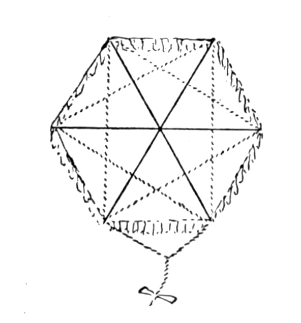
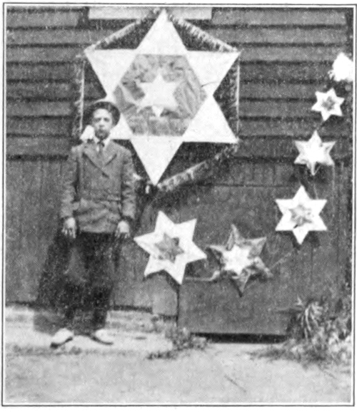
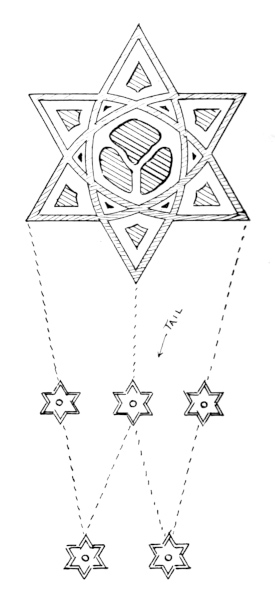
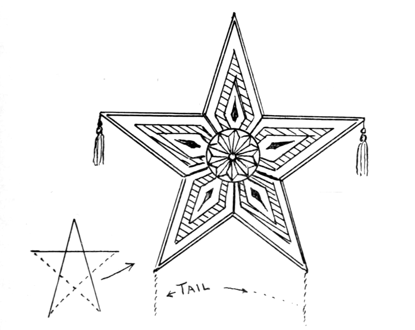
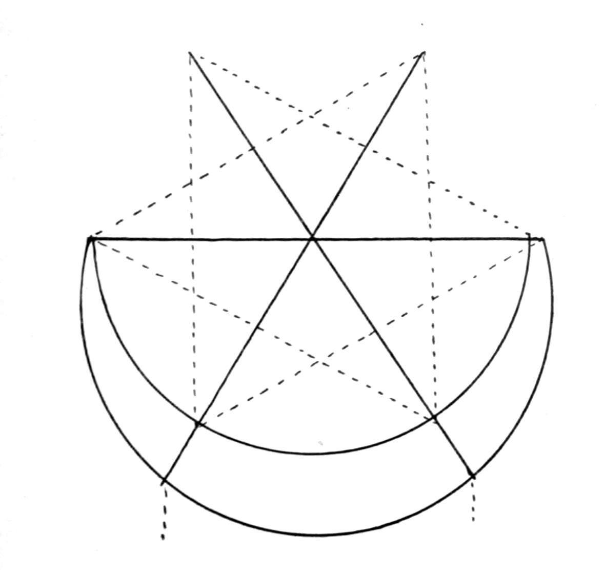
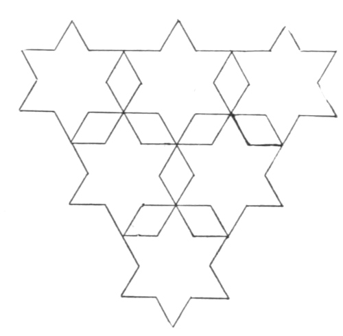
The bridle for a single spine and bow tailless is something attached at top and bottom of spine, or at the intersection of bow and spine, and at bottom of spine. In either case the bridle should be long enough so that when stretched out to the side of the kite while attached at the two points named, it will just reach out to the end of the bow; and at this point the kite line is attached; see Fig. 13. Fig. 33 shows a hexagonal kite. The same framework could be covered as a star kite, Fig. 34. There may be any number of points to a star kite, but most boys make the six-pointed ones. Sometimes the points are arranged as in Fig. 35, and again as in Fig. 33. Fig. 36 shows a very interesting tail for smaller star kites. Fig. 37 has another arrangement of stars for the tail. Fig. 38 shows a pentagonal kite and its construction. The bridle might be attached at one upper point and the two lower points. Fig. 39 shows an addition to the six-pointed star, in the shape of a crescent. Note that two sticks are longer, extending across the crescent, thus giving more rigidity to the surface. The outline of the crescent was made of split bamboo. In a similar manner, a broad circle could be formed about Fig. 38. See 38a.
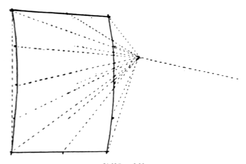
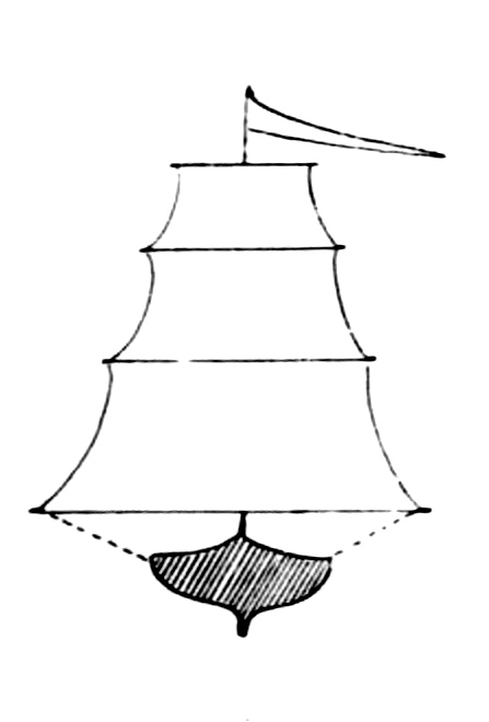
Star and hexagonal kites are not the only members of the regular shapes with tails. The Japanese square kite, Fig. 40, which is usually rectangular in shape, has a vertical spine, two diagonal spines, and several horizontal ribs that are lighter in weight than the spines. The larger the kite, the more horizontal ribs will be required. By making[Pg 30] removable spines the kites can be rolled up and the Japanese have exhibited some very beautiful ones that have been imported. Some of these cost as high as $30.00 or more. The two long ropelike tails swinging in graceful, parallel curves give a beautiful effect to the whole kite. The bridle is usually attached at many places on this kite.
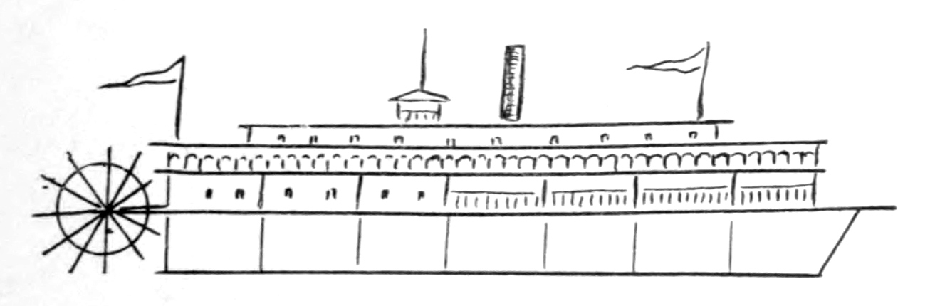
Regular forms of kites are many. In Fig. 41 the circle is of reed or split bamboo. It would be well to fasten the bridle at four points. Fig. 42 needs no special explanation as the construction is similar[Pg 31] to Fig. 41. The balloon kite is another modification. The ship kites, Figs. 43, 44, 45, 45a, show the construction in the drawing. A piece of pasteboard is used for the hull. They make pretty kites.
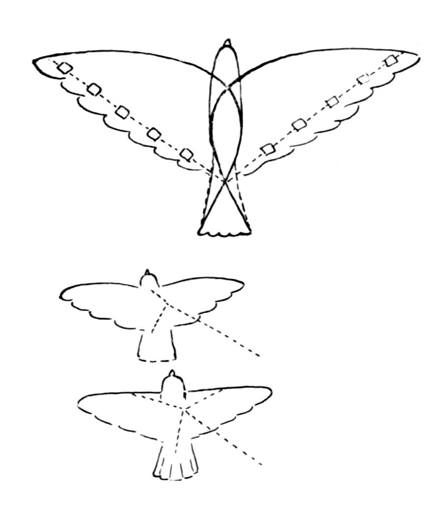
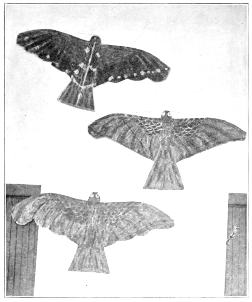
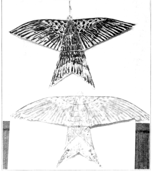
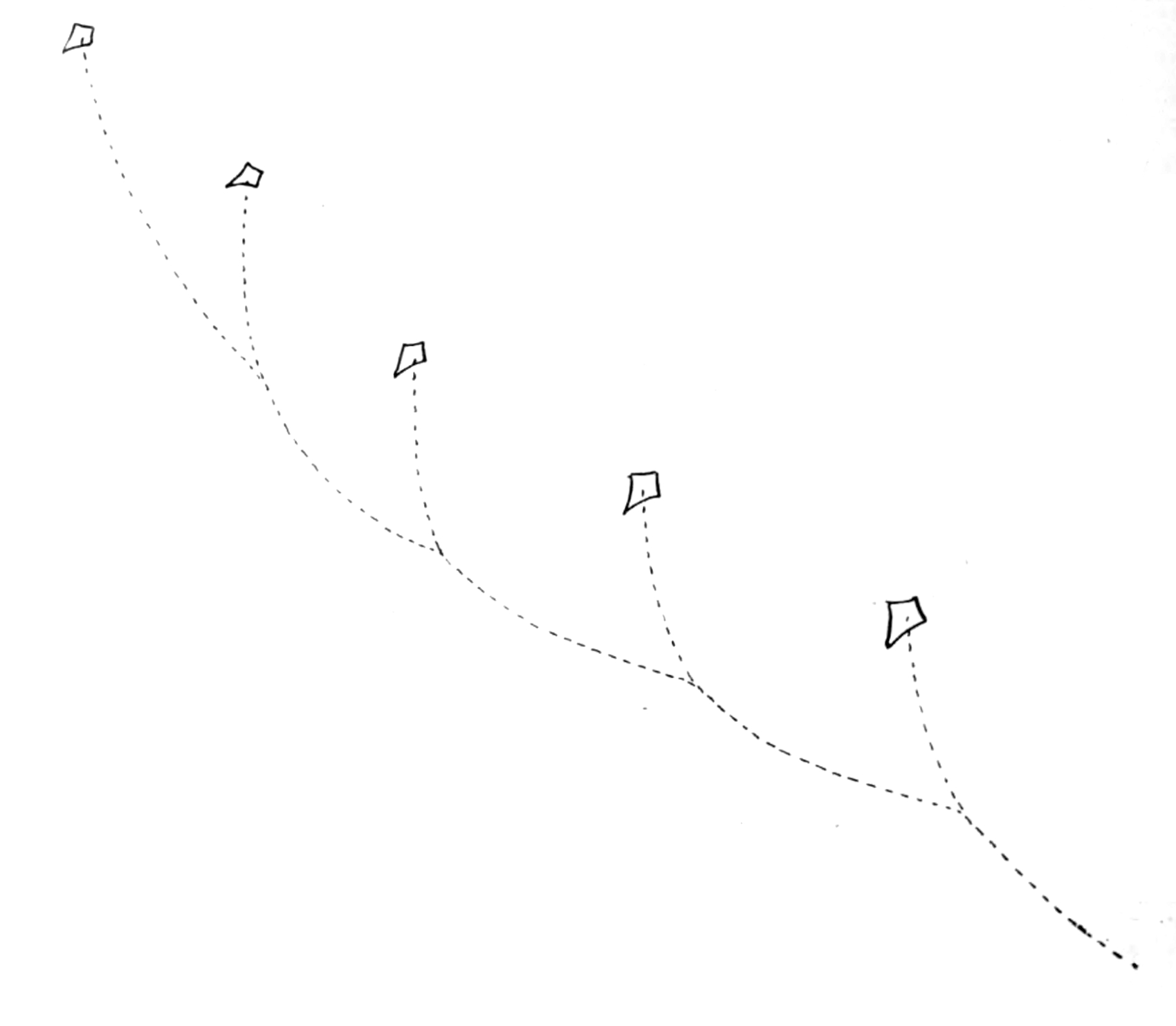
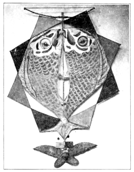
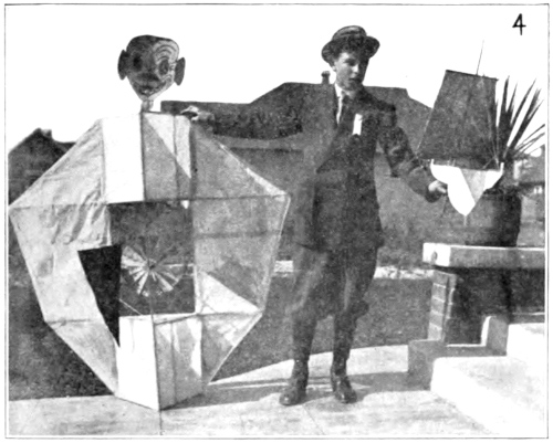
The irregular forms are more representative, and to many, more interesting, because with patience and ingenuity almost any form can be made to float in the air. Soaring birds, Fig. 46, are attractive and their construction is unique. Split bamboo is mostly used for the framework. The Chinese boys take small strips of[Pg 32] the Chinese tissue paper to lash the pieces of frame together. It is very light and if twisted while wet, becomes tight and strong when dry. The covering is also of Chinese tissue and colored with a water color brush. A group of about five of these kites is very interesting when soaring about on high. A pleasing modification is an ingenious tail attachment that is hinged to the body so that the tail drops and is raised again by the breeze, giving the appearance of fluttering when a little distance away. Fig. 47 is a photograph of three that were flown at one time and were mistaken by many for real birds, while Fig. 48 is a photograph of a pair with fluttering tails. In each picture the back of one bird is shown. In Fig. 47 the birds are flat but in Fig. 48 the bodies are rounded out, giving a keel to the kite. This is done by making a light framework of small split bamboo. Notice the little patches of paper on the back that hold the string, allowing the edge of the covering to float and flutter as feathers. The bridle attachment may be two strings, as in Fig. 13, and may be three, as in Fig. 14. A set piece is shown in Fig. 49, with an American flag fluttering as a balancer. This makes a very beautiful kite when enough time is put on it to make the bird stand out clear and real in appearance. One boy cut papers and stuck on to a background for feathers and while he succeeded well it is not necessary and not as effective as a few good strokes with a water color brush.
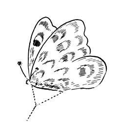
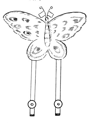
Butterflies offer a great variety in design and color, the best results being obtained by pasting the striking colors over the general covering. A more permanent kite can be made by using the Chinese tissue with strong water colors, and it is more a work of art. A kite thirty inches across, made of bamboo and Chinese paper will last for years if it has good care. Butterfly kites have been made to fly without tails but nearly all need one. Two drawings are shown, Fig. 50 shows the double tail of ribbon and button of cardboard at bottom. The body is curved like the bird form, Fig. 48, and the edge of the wing is scalloped but the waves are longer than for feathers. A Chinese boy made this and placed a small silk Chinese flag on one side of the head and a like American flag on the other. The antennae were pieces of small reed with silk balls that are sometimes used in ornamenting draperies and gowns.
[Pg 33]
[Pg 34]
[Pg 35] Animal Forms. The animals are not limited to bears, but horses, elephants, etc., can be outlined in kite forms. Fig. 52 shows a standing bear with little bears swinging between ropes as balancers for the large bear. The ropes in the kite may be strips of cambric. Small strips of wood should cross from one rope to the other back of the little bears which are made of medium thick cardboard. The bridle can be attached from the bear’s shoulders to the bottom of the spine stick. The bridle is attached only to the large bear.
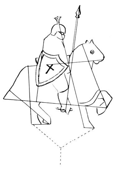
A horse carrying a knight in armor, or horses hitched to a chariot, would take much planning but are within reach. An elephant with splendid equipment of royal hangings would make a gorgeous appearance. When difficult problems of this kind are attempted it should be by kite makers of experience as much adjusting will be necessary, and plans for framework will be needed that will give rigidity and lightness. Some parts in a complex design will need stiffening with reed bent out and around from the framework. Sometimes a small outline may be effected by means of stiff paper and again a string may be stretched from some distant stick[Pg 36] of the framework so as to carry the covering out to certain lines. By careful planning some very complicated forms can be worked out. In the mounted knight, Fig. 53, the nose of the horse will be a straight stick, but the upper line of neck and lower part of head will be bent reed, and of good weight. The raised knee and foot are reed, while the under side of neck changes from the line of the breast by means of a string. The back of the foreleg on the ground is of string, while the extension of the stirrup might be of stiff paper. Much can be done with the brush. For instance, the dropping down of the rump to the tail would be curved, let the outline run angular, then with a heavy streak of color, give form. A little silver paper on the armor will spice it up wonderfully.
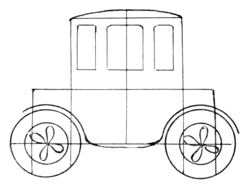
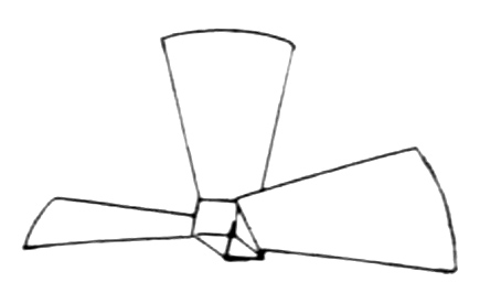
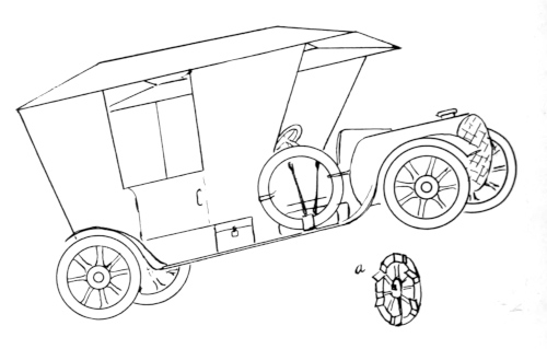
We might consider a mechanical model, an electric coupe, Fig. 54. The tires may be somewhat exaggerated and stationary, while the inside[Pg 38] spokes and hub could be in the form of a small windmill so as to turn around, giving the effect of running. In such case, the fans should be so turned as to turn the wheels in the same direction. By the use of a double bridle and two kite lines, it would be possible to cause the auto to travel across the sky. Electric cars and locomotives might be similarly made and manipulated.
When reed or bamboo are to be bent for some very particular form, it might be well to lay it out on a board with brads on each side, leaving it to dry. In this way a truer form may be secured. Bamboo can be bent into shape by a little heating over a flame.
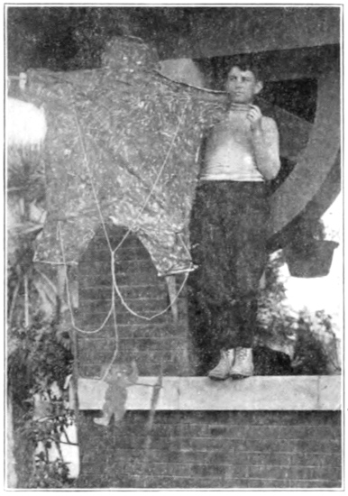
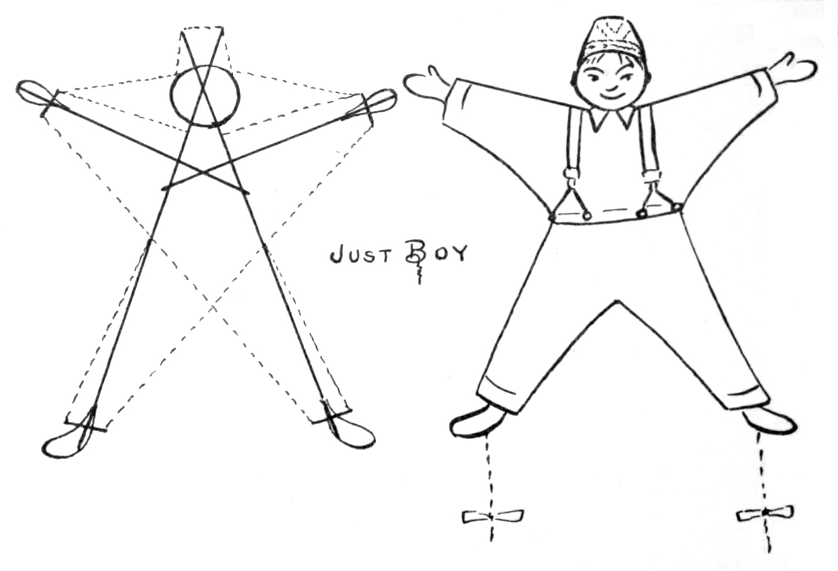
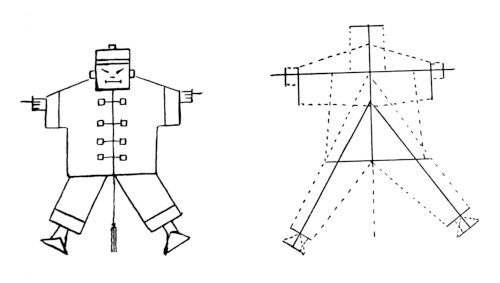
The human kite has all the possibilities of caricature in it, and there are some very funny attempts. “Just Boy,” Fig. 55, is a good one, and “Foxy Grandpa” is popular. Fig. 56 is the “Squared Chinaman”. The “Clown and Donkey,” Fig. 57, is rather easy, being a combination of three tailless kites. The “Dutch Girl” makes a good kite, also “Me Happy,” Fig. 58. In these as in the previous sub-group, much of the effect is dependent on skilful handling of brush, after the kite has been constructed. The flying depends much on the attachment of bridle and balancers.
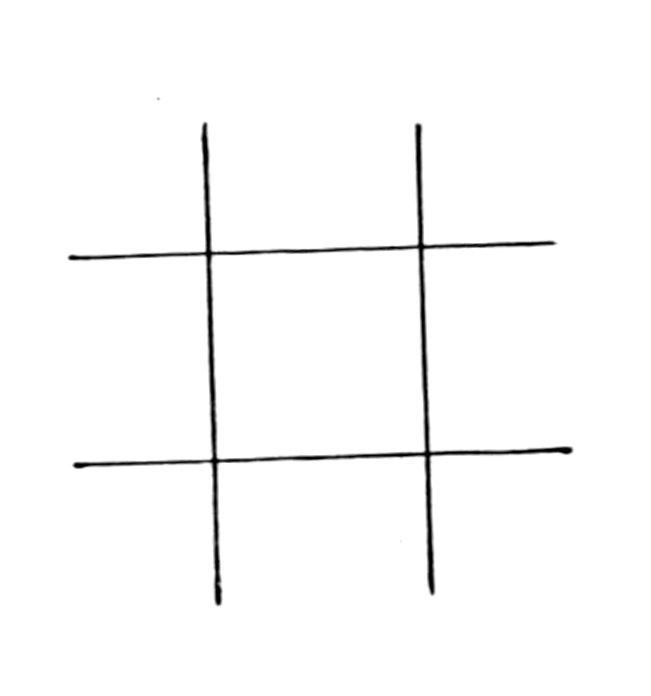
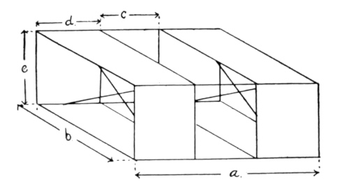
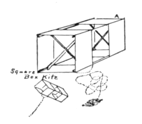
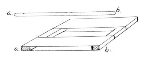
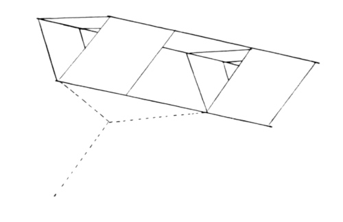
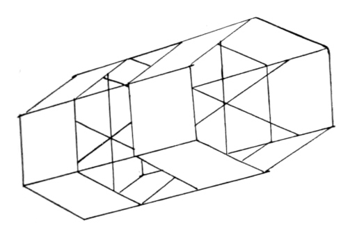
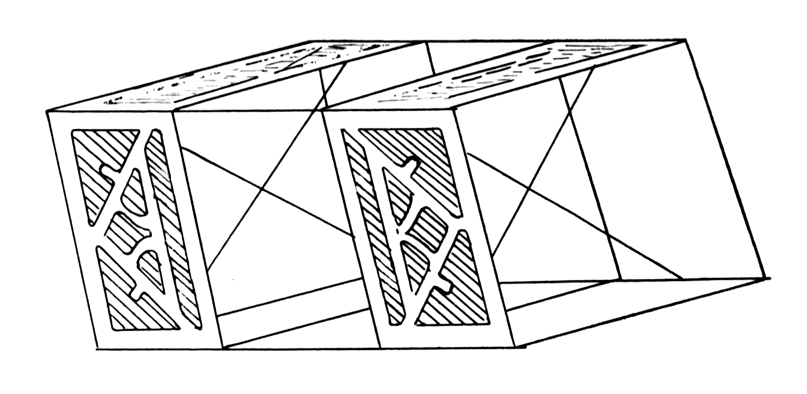
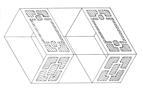
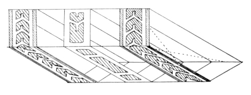
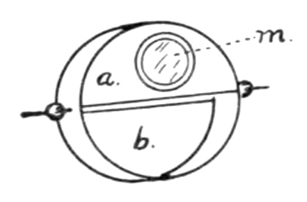
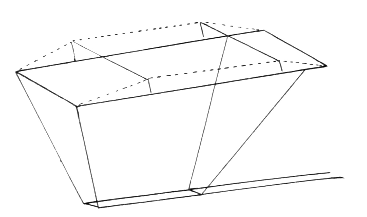
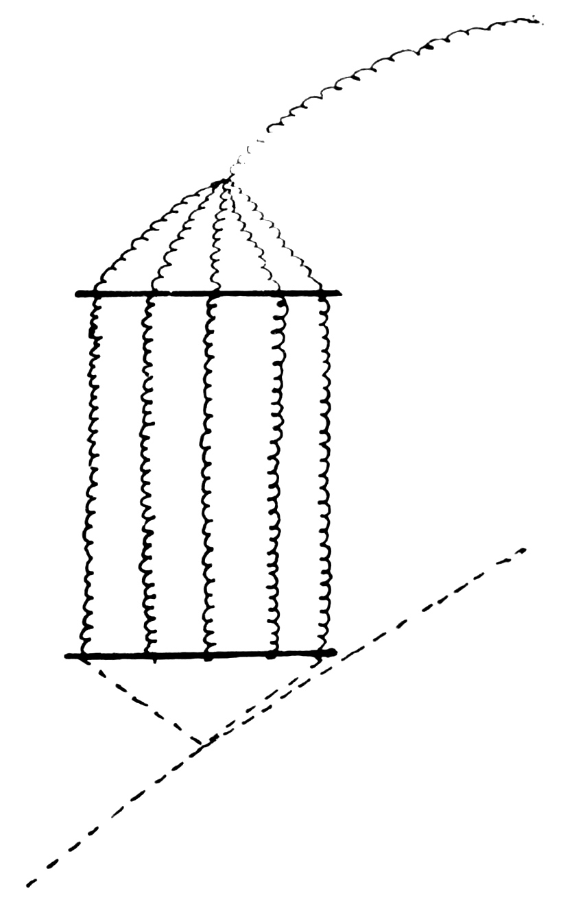
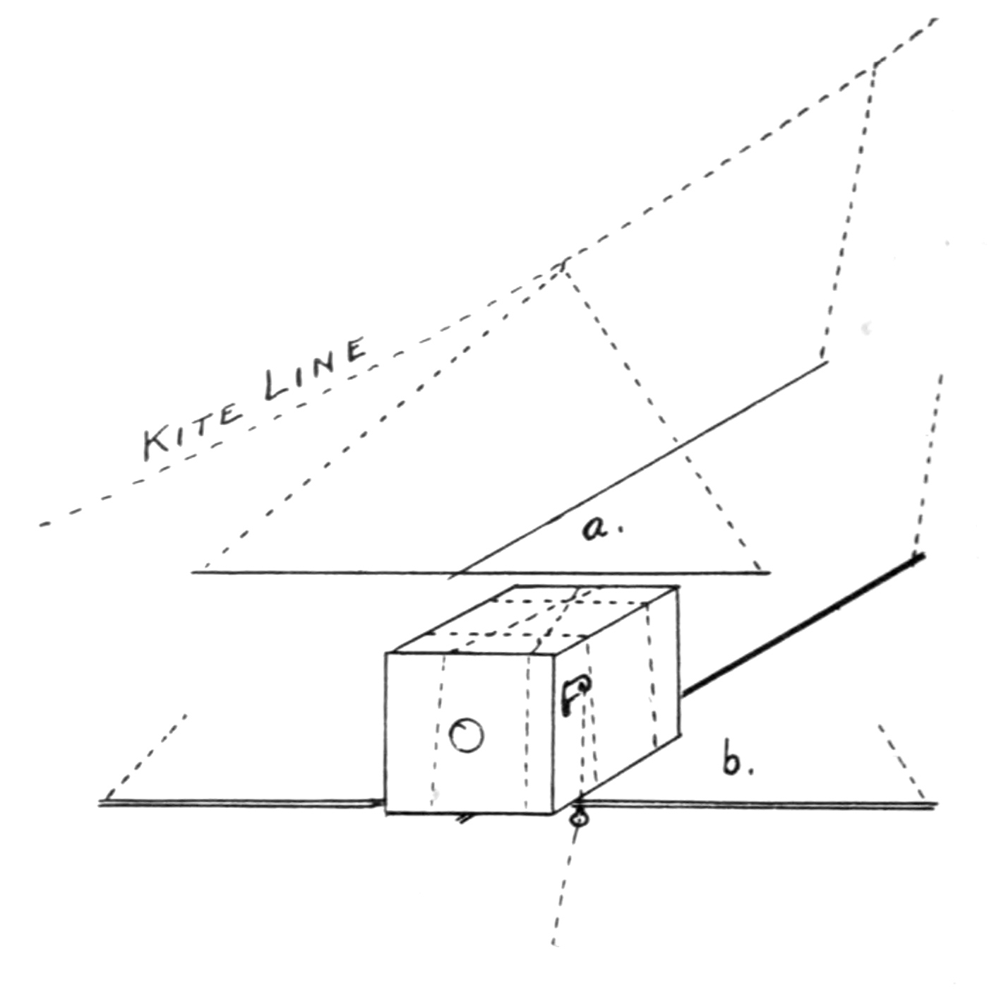
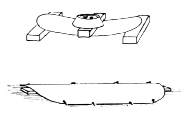
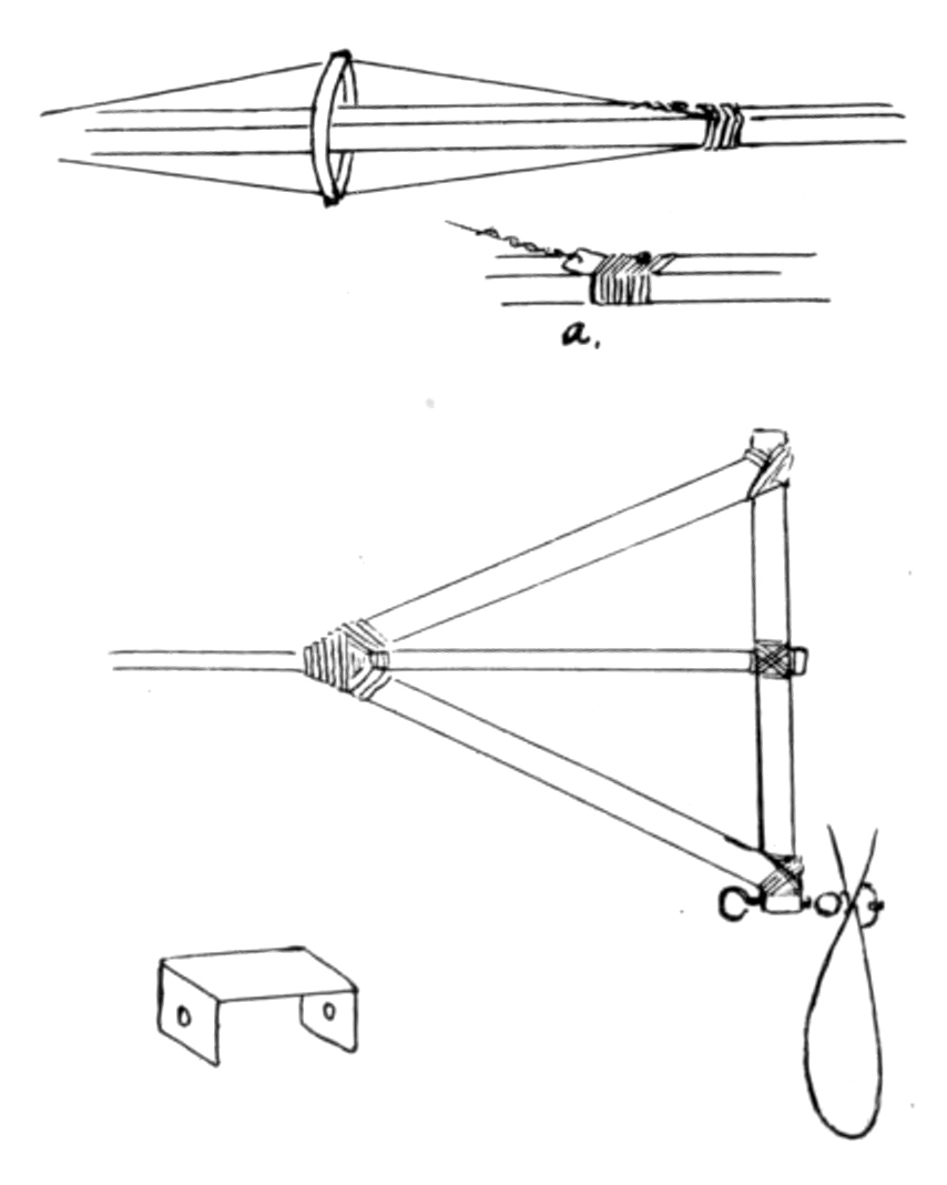
Box-kites were a new invention a very few years ago. People said, “No use trying to put a drygoods box up in the air,” and yet something very similar in shape has been successfully used for a number of practical purposes. The box-kites usually require more breeze than the plain surface kites, but are stronger pullers, which means also heavier lifters than their lighter breeze cousins. Before entering the discussion of box-kites, it will be well to understand some terms that are used quite generally by all kite enthusiasts. Fig. 59 is a plain two-celled box-kite; a, is the length of the kite. The framework consists of four sticks, one at each corner, and four braces, two near each end of the kite, placed diagonally across the inside of the kite from one corner stick to the other. The covering consists of two bands passing on the outside of the four corner sticks, one band at each end.
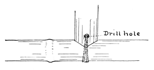
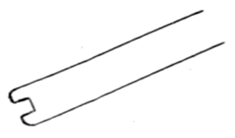
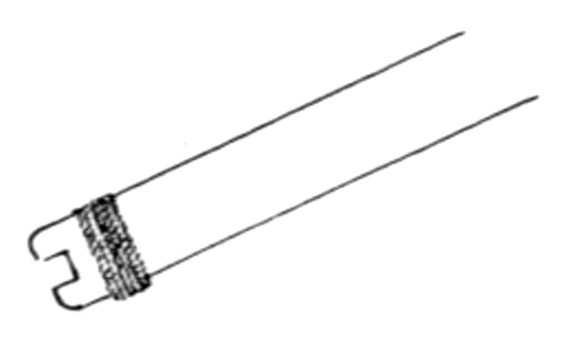
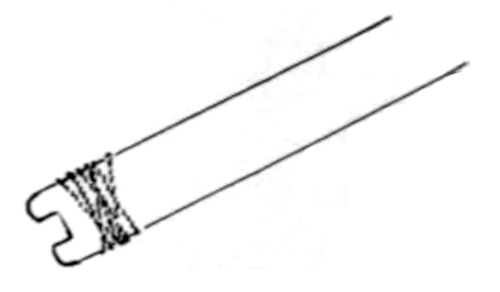
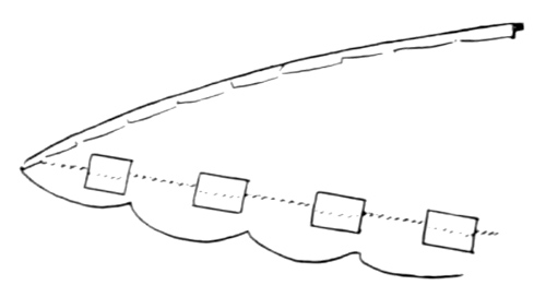
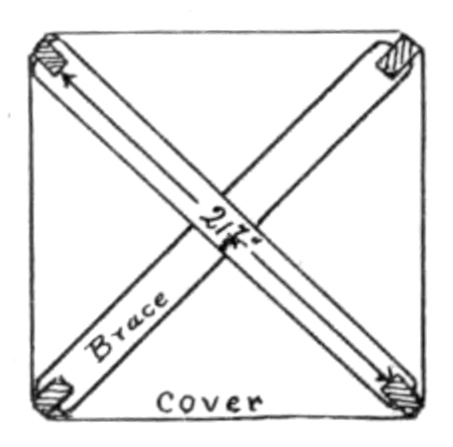
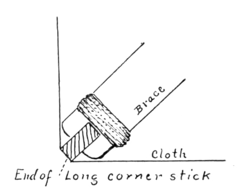
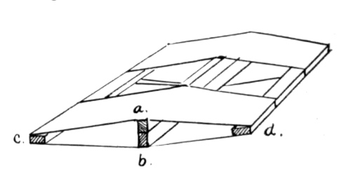
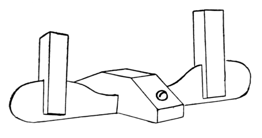
The band and space enclosed is called a cell of the kite. So this kite has two cells. The length of the cell is the same as the width of the kite and is represented by b; the depth of the cell is the same as the height of the kite in its present position, and is shown by letter e; the breadth of the cell by letter d; and the distance between cells, c, is called the vent. Nearly all box-kites require the vent, and the vent is usually wider than the breadth of the cell. Usually the two cells, the fore and aft, are the same size, but not necessarily so. No one would be seen flying a box-kite with any kind of tail unless that had a purpose in carrying out the design. The square box-kite, Fig. 60, is square in cross-section, is very serviceable for flying, and is convenient for carrying. It is usually made to fold up, and the bridle is attached to one corner piece of the frame. This kite flies diagonally in the air. It is quite easy to attach the bridle to two corner sticks of the frame, when it flies horizontally, Fig. 61. Lining cambric is good for covering and some bright color should be used; but some prefer a good wrapping paper. Chinese tissue may be used if the kite is not too large. The corner sticks stand diagonally in the corners of the kite so that the notches of the braces can fit over them, see Fig. 62. The drawing[Pg 41] represents the end of the kite, with the corner sticks stretched apart. Fig. 63 represents a part of one of the braces. String and glue are used back of the notch to prevent splitting when the strain is put on them up in the air. The braces are made just a little long so that they bow a little when in place, and this stretches the cover tight.
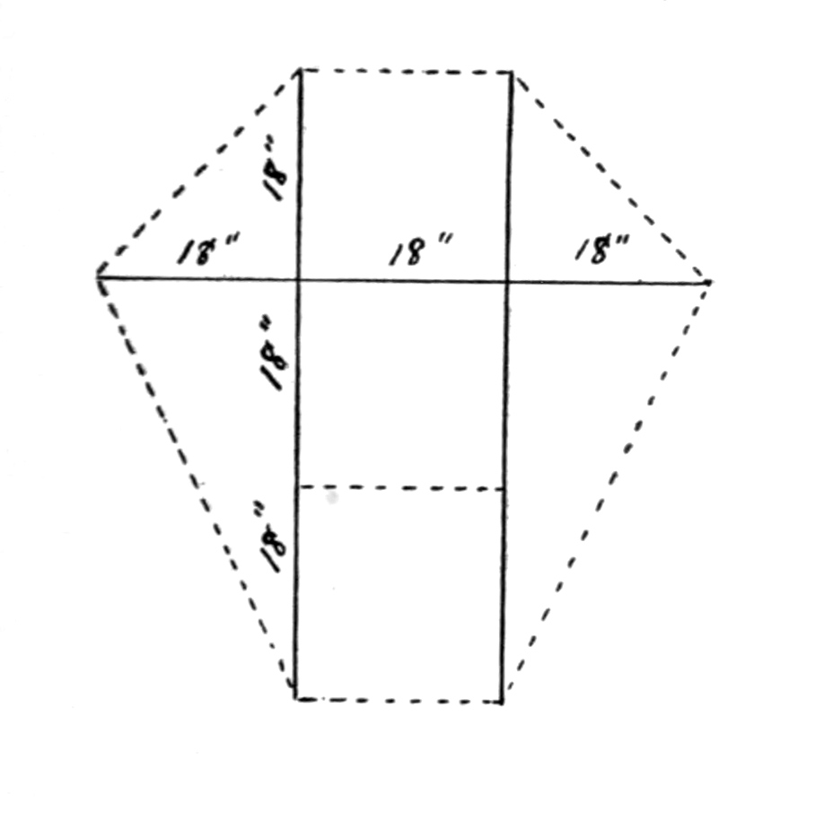
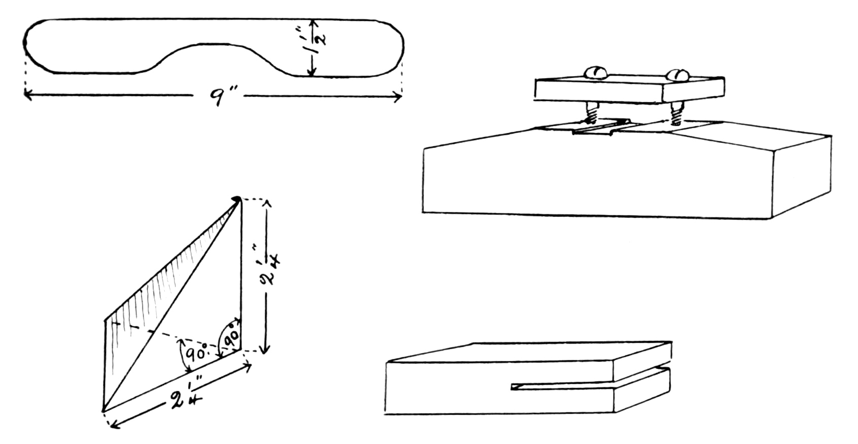
A word about getting the cover on the corner sticks may be in order. The distance around the kite is determined, and a band is made the right width and the right length to reach around when the braces are sprung to place. Stretch the band out like a rubber band, Fig. 64, and put in two corner sticks at a and b that have previously been glued on one edge, and allowed to partially dry until it is what is called tacky. Now the band at the other end should also be glued in place when the progress will show as in Fig. 65. Remember the glue is only on the outer edge of the sticks. Now find and mark the exact center between the sticks glued in place and fold to these two lines, and glue in the other two sticks in a similar manner. The progress made will be as shown in Fig. 66. When the glue is thoroly dry, the kite is ready for the braces and for flying. The braces might be tied together where they cross each other. A good size for the corner sticks is 3/16” × ½” × 36” with bands 10” wide and 64” long, plus 1” additional for the hem. This will give 16” for each side. Enough will be needed additional in width so as to allow a ½” hem for each side. Each band then will require a strip of cloth or paper 11” wide and 65” long. With paper bands the ½” should be folded over and a string should be glued inside to strengthen the edge. The braces should be ⅛” × ½” × 21⅞” from the bottom of one notch to the bottom of the other, see Fig. 62.
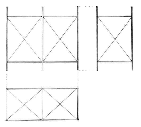
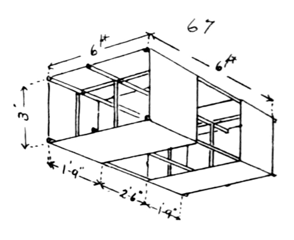
Rectangular Kite. The next is the rectangular kite, as shown in Fig. 67. This is a splendid kite of its kind and should have specific measurements. The two center pieces called the spines are ⅝” × ⅝” the corner and cross-pieces ⅜” × ⅜”. The bands for cells are 21” wide by 18”, with 1” additional for the seam. The edges should be hemmed as in previous kite. The framework should be all thoroly wired in every direction as shown by drawing, Fig. 68. Little wire turnbuckles such as are sold by firms carrying model aeroplane supplies might be used, and the stretch of the wires could be taken up from time to time. A[Pg 42] well made kite will last a long time if it has good care. This particular construction is for large kites and they are not often made to fold, altho it is possible to make them so. Out of the box-kite has grown the aeroplane. Some good sizes for kites are:
Six-foot kite:—6’ long, 6’ wide, 3’ deep, 1’9” width of cell, ⅝” × ⅝” corner-pieces, 2’6” between cells, ⅝” × ⅝” spines.
Nine-foot kite:—9’ long, 9’ wide, 4’ deep, 2’6” width of cell, ¾” × ¾” corner-pieces, 4’ between cells, 1” × 1” spines.
Twelve-foot kite:—12’ long, 12’ wide, 6’ deep, 3’6” width of cell, ⅞” × ⅞” corner pieces, 5’ between cells, 1¼” × 1¼” spines.
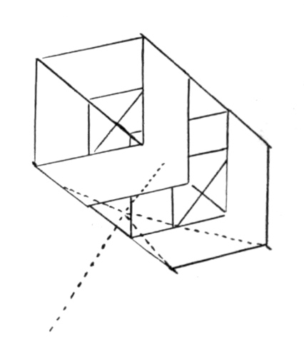
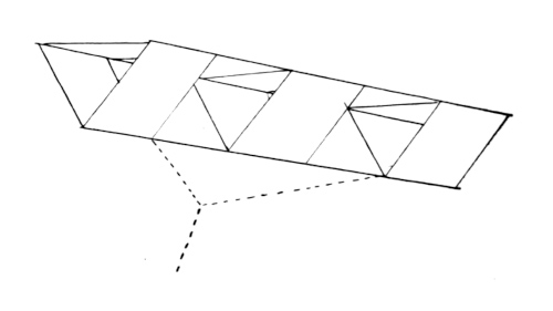
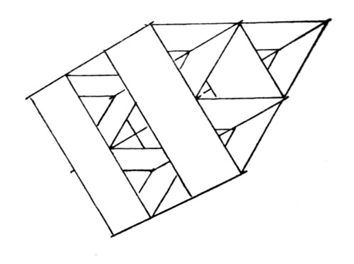
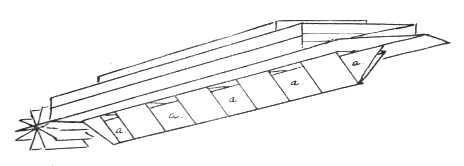
The two kites just described may be modified in a number of ways as follows:—Two square kites side by side will give Fig. 69, and three side by side Fig. 70; these might be increased in both directions until a[Pg 45] kite like Fig. 71 might be evolved. But there is no great gain and much hindrance in some of these complications. If there is insufficient room between upper and lower surface, not all of the surface is exposed and there is skin friction, again if there is not space enough between the fore and back cells, the front cuts off the air pressure to some extent on the back cells. So Fig. 72 is not high enough, while Fig. 73 has the fore and back cells too close together. Fig. 74 is very unstable in the air.
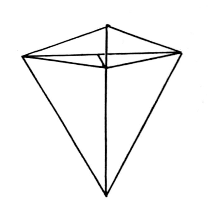
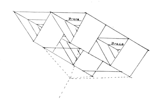
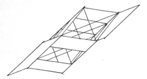
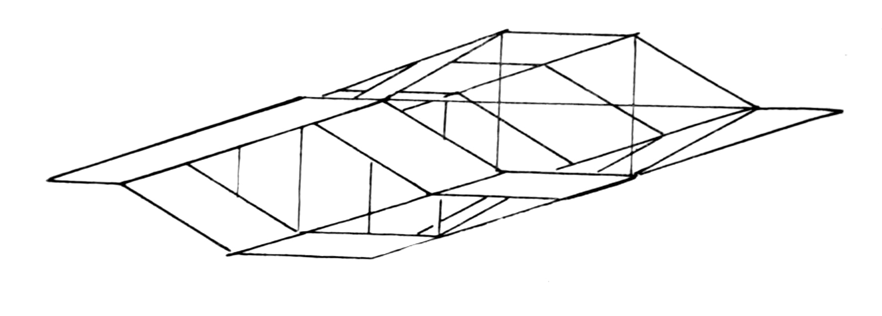
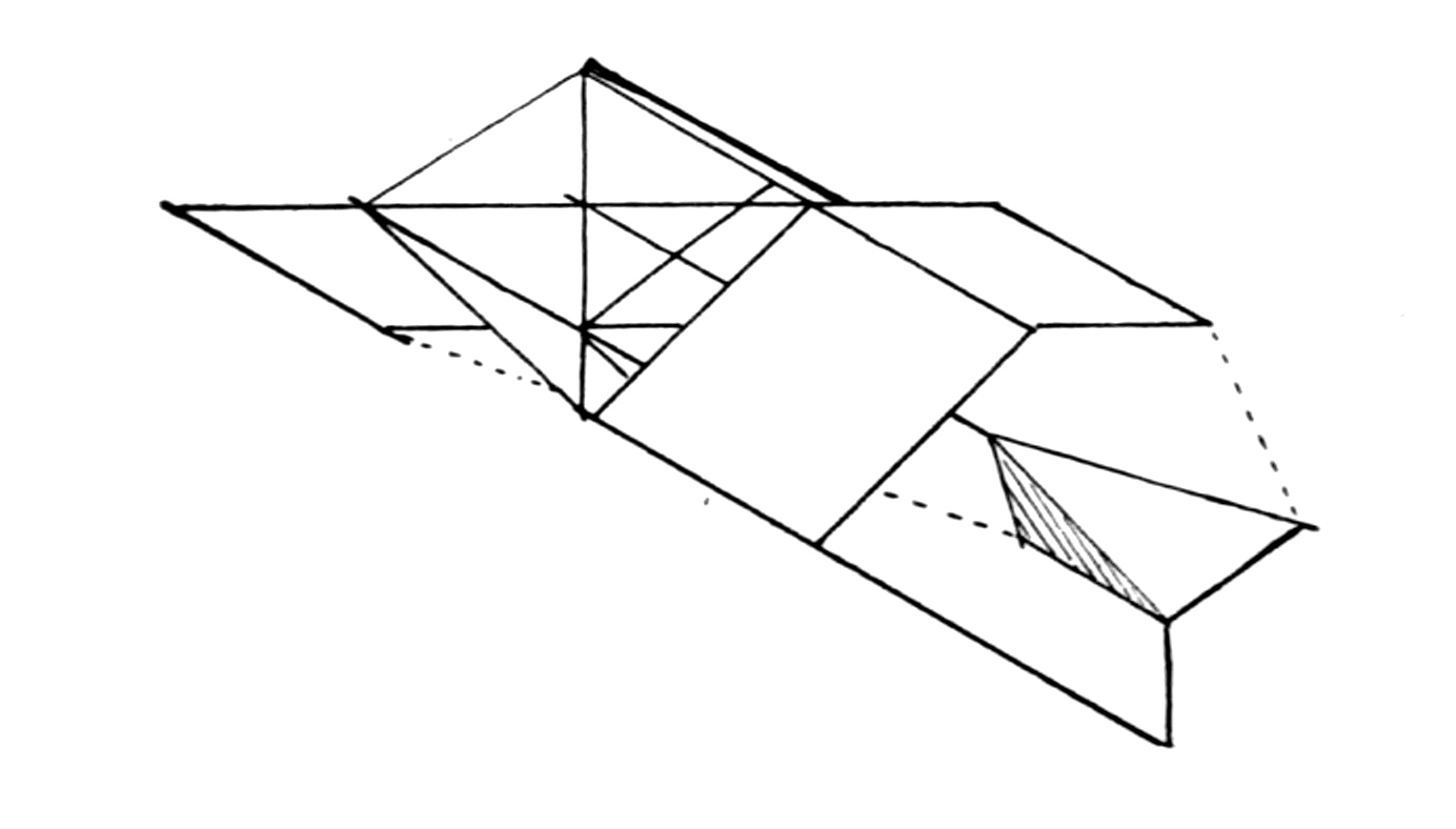
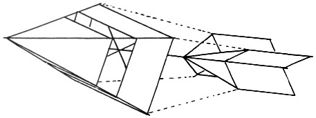
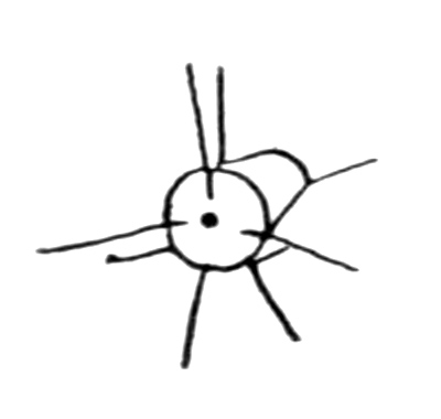
The triangular cross-section has the advantage of a bracing framework and is easy in combination. The bridle is attached to one of the long sticks and the kite rides on a keel, Fig. 75. Three braces about the middle of each cell keep the corner sticks out to place. These can be put in at the field, thus allowing the kite to be rolled for transportation. The triangular kite is sometimes lengthened so as to use three cells, Fig. 76, and again two kites are placed side by side, Fig. 77, and this may be increased by placing another below both, as in Fig. 78. In the last combination we have a large kite to the outside and a smaller one to the inside which can be lengthened so as to give three cells in length, Fig. 79, and many other combinations can be made.
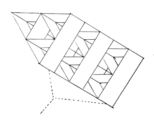
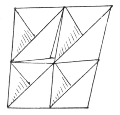
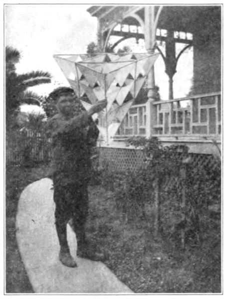
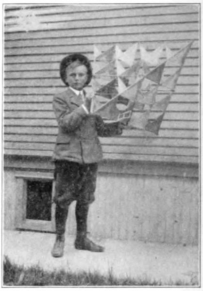
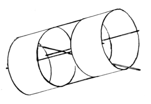
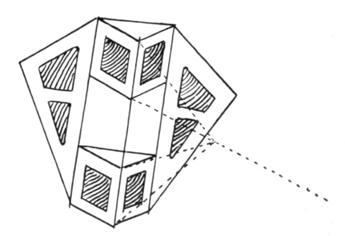
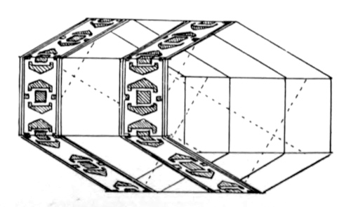
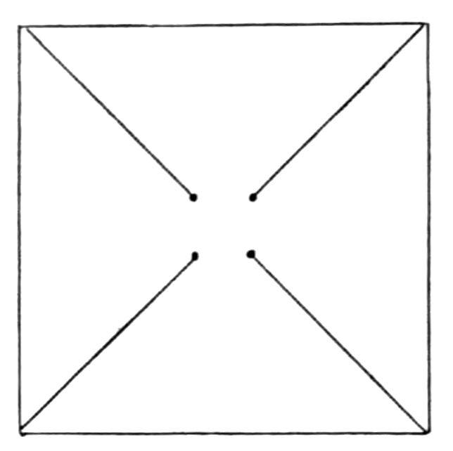
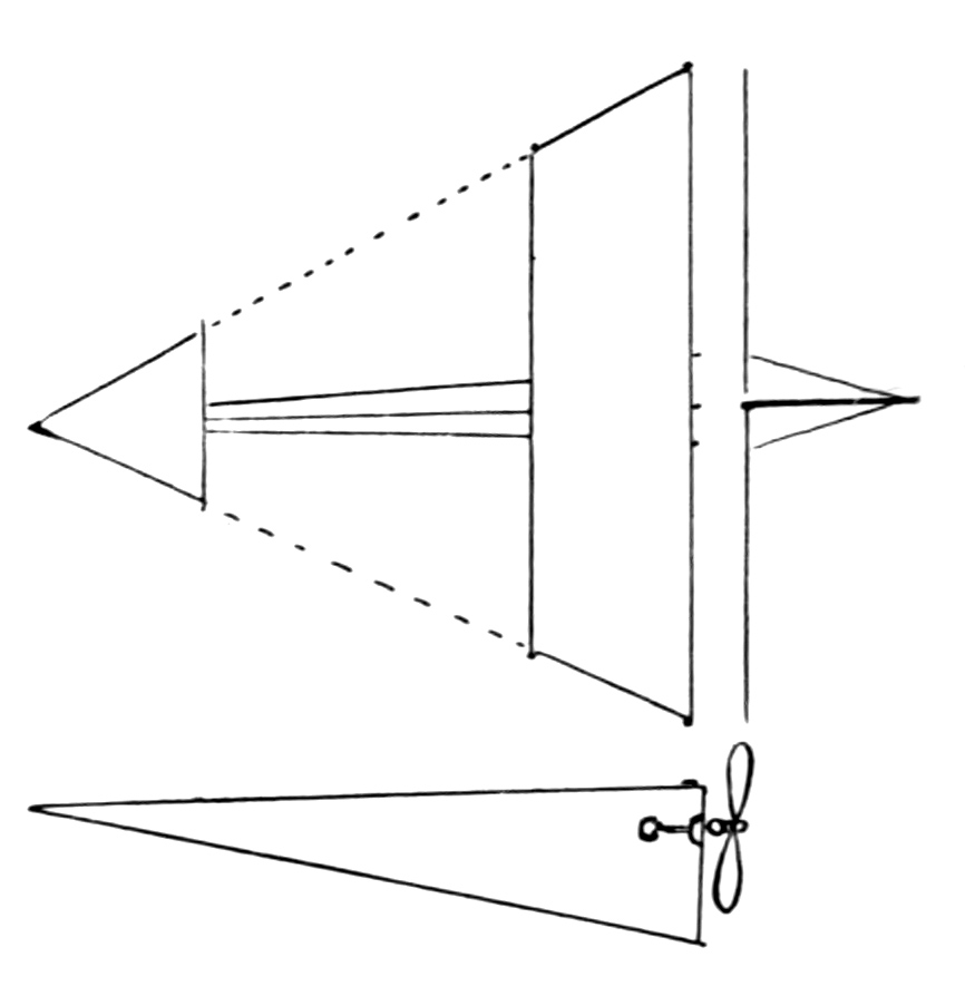
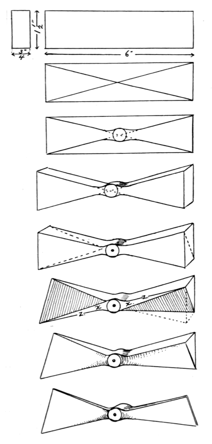
Tetrahedral Kite. Out of the triangular has grown the celebrated Bell tetrahedral kites, which can be increased in size beyond that of any other kite. No attempt will be made to give an exhaustive description or full construction of these wonderful kites as Dr. Bell has written a number of good articles on the subject for the Scientific American and other magazines. There have been some wonderful kites made on this principle of construction. In simple kites of this construction we have a large tetrahedral frame composed of six sticks, Fig. 80. Owing to the bracing effect, remarkably small material can be used. For a kite four feet to an edge, 3/16” sticks were ample. All of the drawings given[Pg 46] here represent the kite resting on its keel, tho a kite left in that position would topple over unless supported in some way. Now we will divide this large tetrahedral horizontally by four sticks, Fig. 81, and in Fig. 82 strings are run from the ends of the four horizontal sticks to the middle of the keel, also to the middle of the upper ridge stick. Some use sticks in place of the strings, but if the kite is not too large the strings are as good and in small kites better. Fig. 83 shows a four-celled tetrahedral with the coverings on. Fig. 84 shows a further division in which each cell of Fig. 83 is again divided into four cells, making a 16-celled kite. The kite rides in the air tipped as shown in Fig. 85. Look up some of the articles given in the “Bibliography of Kites” for further discussions of this type.
The hexagonal kite is also an outgrowth of the triangular. Looking at the end of a hexagonal kite, three brace sticks will be seen, Fig. 86, which can be made removable, thus allowing the kite and its covering[Pg 47] to be rolled. The kite will be more stable in the air if one side is down, so the bridle will be attached to two of the long sticks, and if it proves unmanageable, at four points.
The circular cross-sectioned or barrel kite is more of a curiosity. It has two cells, and the frame is made up of four circles, either of split bamboo, reed, or thin tough wood. The circle should be shaped before further construction is attempted. Most of the strain will come on the circles so the ribs, connecting the four circles, may be quite light and slender. There will be less danger of twisting out of shape if more than two ribs are used. The ribs should be lashed to the rings with thread or twisted paper. No braces are necessary in the small ones; a long stick slanting thru the entire kite may be used in the larger ones, see Fig. 87, with covering.
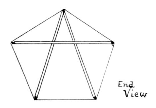
A pentagonal frame could be constructed with three braces, Fig. 88, and should be flown in the position shown.
COMBINING PLAIN SURFACES AND BOX KITES TOGETHER.
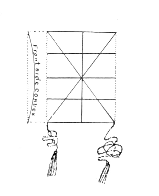
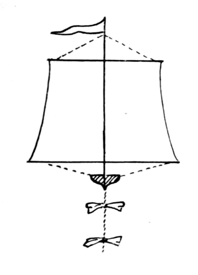
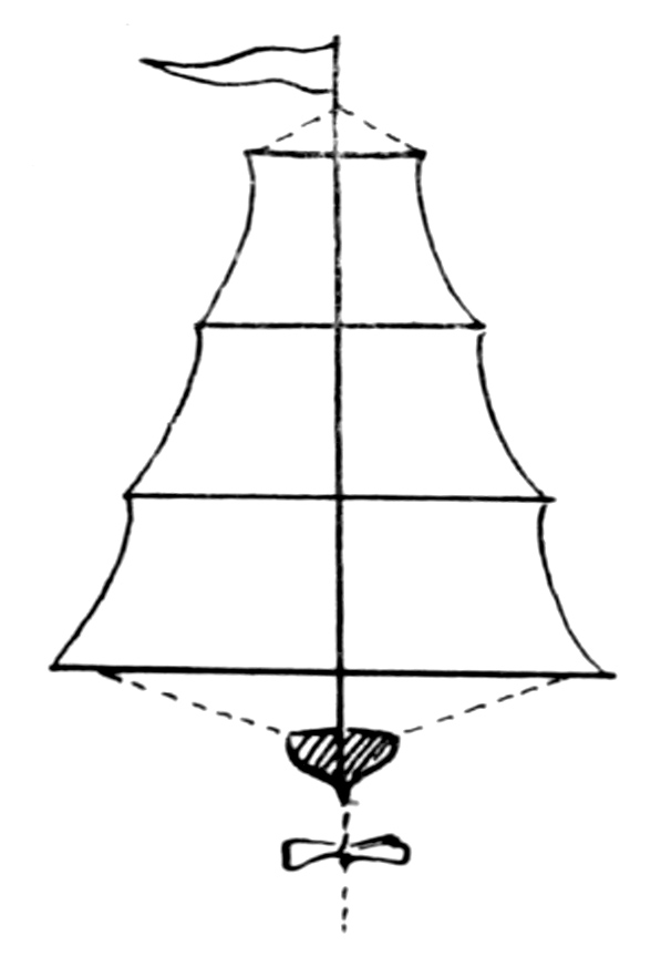
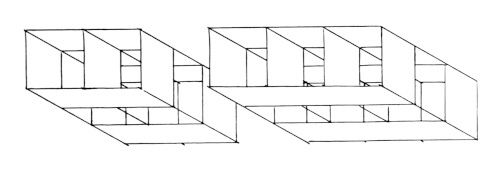
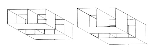
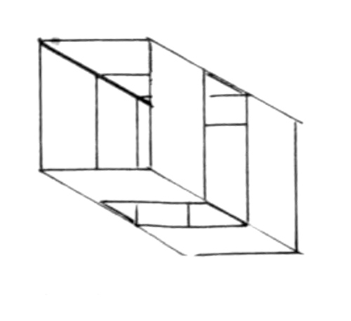
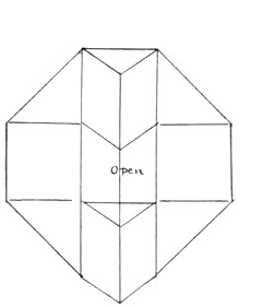
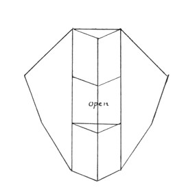
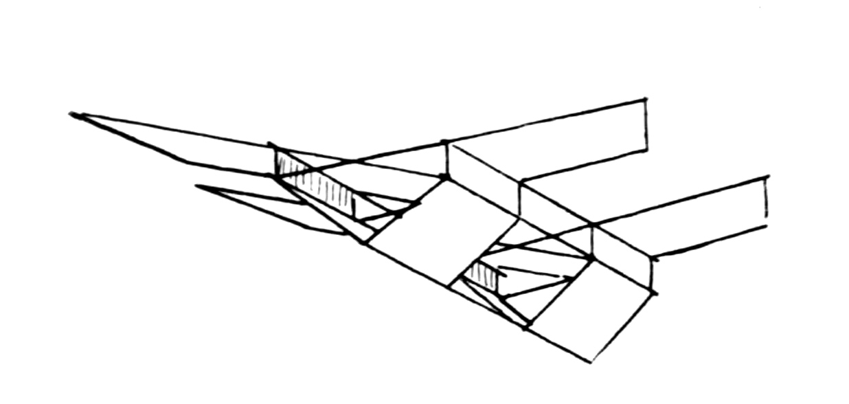
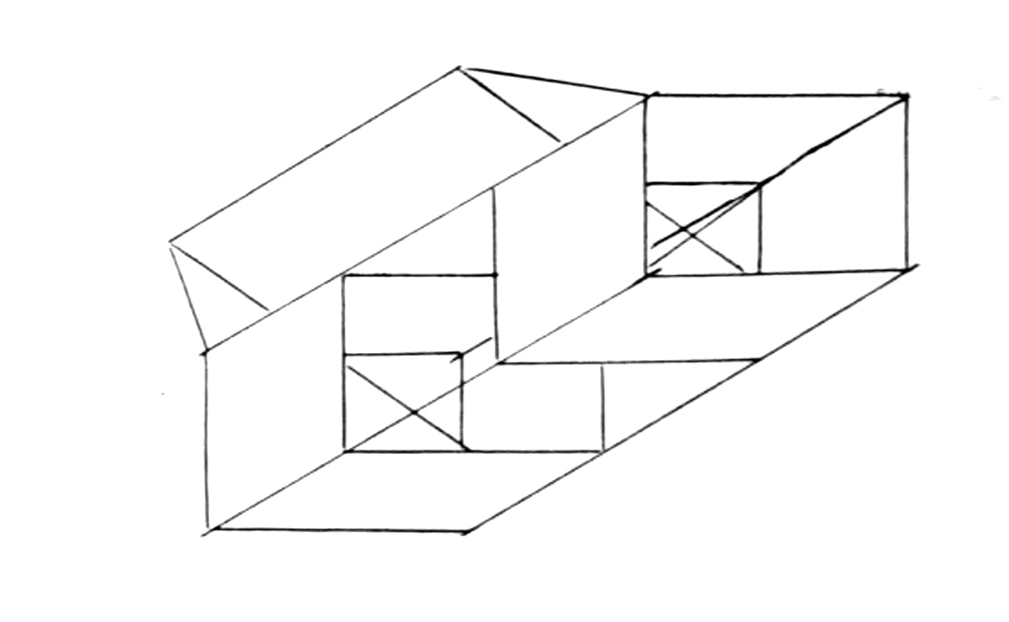
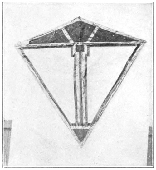
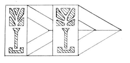
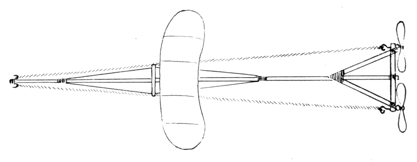
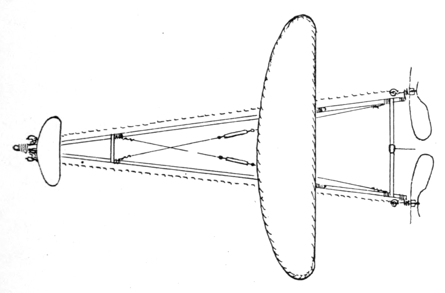
Straight Extension of Surfaces. One of the most efficient and popular kites in the combined construction group is the two spined tailless, called the house kite, and the triangular box-kite, as shown by Fig. 89. This is an easy kite to make and the proportions are easy to remember. The simplest plan is shown in Fig. 90. Three sticks of the same size are used; say, ⅜” × ½” × 4½’. The horizontal stick is lashed to the two vertical spines down one-third the distance from the top, in this case 18”. The two spines are also 18” apart, which leaves the extension of the horizontal 18” to each side of spines. Now run a string around the outside of the framework, and cover as in Fig. 91. The two cells are now built over the two spaces between the spines. There need not be any braces for these cells, but another stick of the same dimensions as the other three is used to keep the keel shaped portion in place when pulled out by the breeze. The whole framework can be built rigid, using two short braces about the middle of each cell out to the fourth stick or keel of kite; the best way, however, is to make the horizontal stick removable and without the short braces so that the kite may be rolled up. Remember there are only four sticks in such a kite and they are all the same size. This kite is sometimes called the “Coyne Kite,” again the “French War Kite,” and is a steady flyer and a strong puller. The bridle can be adjusted so as to give much or little inclination to the breeze. For lazy, easy gliding, the kite would be adjusted as in Fig. 92, or with the lower horizontal shorter, as in Fig. 93. The horizontals[Pg 49] may be bowed forward and also backward. We have had all sizes of this kite at the tournaments. Fig. 94 is about five inches tall, while another was sixteen feet tall and required quite an army of boys to pull it up in the air.
A similar combination can be made with the square box-kite on the diagonal with straight surfaces out to each side, as shown in Fig. 95. Besides the four vertical sticks, there are four horizontal pieces of the[Pg 50] so as to be nearer horizontal. This kite can be modified by a lower horizontal two-thirds down of the same length as the upper horizontal, as in same length and one short brace placed centrally in each cell to keep the fore and back sticks apart. The short braces can be notched to slip into place and on being removed will let the kite down flat. This kite will need to be more rigid than the one just described. A hexagonal box-kite could be made with side wings by extending one of the braces at each end, Fig. 96, and the pentagonal form could be similarly modified. Fig. 97 has a little different plan of extension that looks more like wings. A triangular box-kite is used as the main structure to build on. Three long sticks are required with four short braces on each side, eight in all, with eight wing sticks, four long and four shorter, that are attached to an inner long stick of the box-like portion and extend across to the short brace of the opposite side. When a pair of the extension sticks are fastened to place, they are lashed together at their crossing point. The slanting extensions are strongly built and add poise to the kite.
The poise of a rectangular kite may be increased by the addition of slant extensions. The extension pieces start from the lower corner pieces, pass under the upper corner pieces, lashing fast at both places, Fig. 98. If a little variety in outline is desired, split bamboo or reed could be used to make such forms as are desired; even string connections can be made.
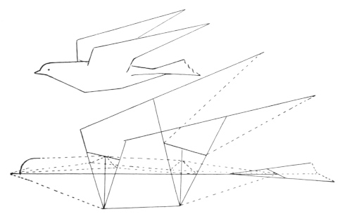
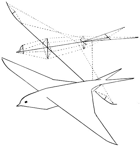
In making hollow form objects both patience and skill are necessary. A form that is interesting but not representative of any real object is shown in Fig. 99. Another is the arrow kite, Fig. 100. The flying bird kite should make a good problem for some ingenious chap. The framework and stringing is shown in Fig. 101. The cross-section of the body of the bird is about the shape of a tailless kite. The plan gives such good bracing construction that very light material may be used. Four feet would be[Pg 51] a good length for this kite. The soaring bird, Fig. 102, is quite similar in construction to the preceding kite. The body is never square in cross-section. A little bow is given to the tip ends of the wings. The back line of the wing changes by means of an extra cord. This kite is not as stable as “The flying Bird.”
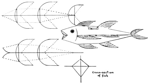
The “flying fish,” Fig. 103, needs vents, as the whole body is a box-kite. Two views of the framework are given; a center spine runs the entire length of the fish with two curves at the mouth. The mouth is left open, so string is used for the outline. The original kite was very mechanically made. It was beyond amateur work and showed that some skilled workman had assisted. Much can be done with the brush to make this a very interesting kite. Scales can be painted and the fins and tail lined up. Wherever vents are placed, there should be a string for the edge of the paper to turn over, or it will tear out.
The “Clown and Donkey,” Fig. 57, is the combination of three tailless kites, and is what is known as a compound kite. Fig. 104 is another example of compounding. Fig. 105 shows a star kite compounded together.
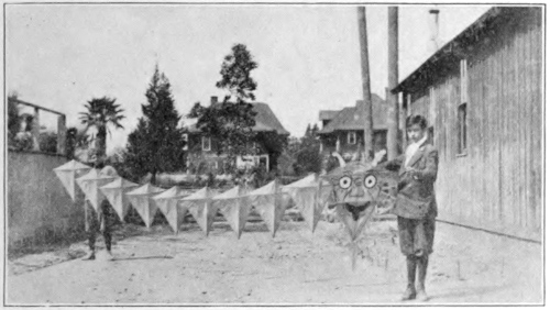
Kites in Series. A boy may put up a kite about five hundred feet, and if it is a good flyer, tie the kite line fast and put up another on perhaps three hundred feet of string. If the second is also a steady flyer he can tie the end of that kite line to the first and let out perhaps three hundred feet more of the first line, and again tie it fast. Another kite is added in the same manner as the second and so on. The best flyers of the series should be placed as leaders. Boys have put up as high as forty kites in such a series, and no one has any idea of the beauty of such a series, when looking up from the standpoint of the flyer, until he has actually seen such a combination. Some prefer to take a color scheme and use it for all the kites, others prefer a great variety of colors, and it is hard to tell which is the most pleasing. Tailless kites are used more than any other[Pg 53] for such purposes. Fig. 106 shows the arrangement. This is one of the best schemes for high flying. The first kite should not be put out to the limit of its lifting power else when the rest of the string is lifted it will not mount up higher. It should have considerable reserve when the second kite is attached. For high flying, the kites should be placed farther apart, and the first part of the line should be light and strong and the thickness increased as needed for strength of the combined kites. Kites can be put up to a great height in this way. This way of combining kites is called “Kites in Tandem.”
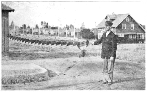
[Pg 55] Another way of flying kites in tandem is to fasten all kites directly to the one kite line, the line passing thru each kite after the first. This method however requires a helper for each kite and they are placed closer together. At one of the Los Angeles Tournaments, two boys had a beautiful team of green and white kites arranged in the second series of tandem. The kites were of the triangular box and house kite order, Fig. 89, were six feet and nine feet tall, and were nine in number. There was insufficient breeze to fly them well, but it was great sport for thirty or forty boys to run with the kite line. They were strong enough to lift up a large man. The heaviest pull that was registered was a little over two hundred pounds, but in a good breeze they would have pulled over four hundred. I would like to show you a picture of them, but I failed to get one.
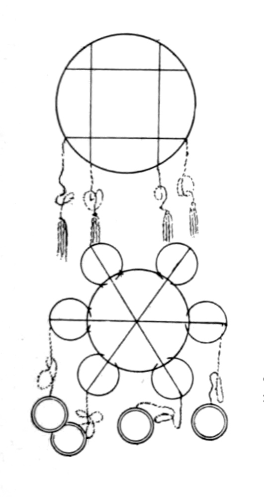
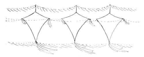
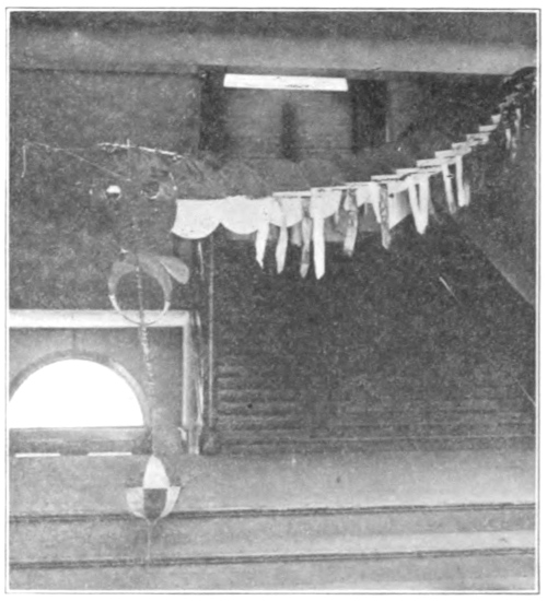
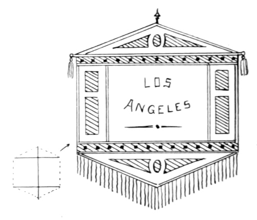
In the second series of tandems, while all kites are attached to the same line directly, there is an individual bridle for each kite, but in the third series we have a sort of harness that combines all kites together, so that if one tips forward, all tip forward, and vice versa. It will be seen that in Figs. 107 and 108 where a number of tailless kites are arranged in a regular series, that there is a complete harness running from the larger kite as a head, to the banner floating[Pg 57] out at the rear. Four cords are attached, one at the top, another at the bottom, and one at each side. The distances between all points are the same, so when the head tips forward, the second kite has a similar inclination to the breeze, and so on thruout the whole series. The bridle is attached at the four points at the head, so attached as to give a good flying inclination. This series is called a “Tailless Dragon Kite” and flies well and makes a fine appearance in the air. The tailless dragon can be made more ornamental and seem more connected, by extending the spine above the kite as in the head, a string with a feather edge of tissue paper being festooned from the top of one kite in the series to the next. At the bottom of each kite some streamers of tissue paper would help in the same manner, Fig. 109. The regular[Pg 59] Chinese centipede kite, Fig. 110, is not so difficult now that we have harnessed the tailless dragon.
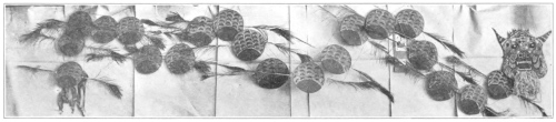
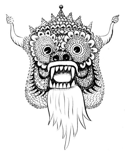
The Chinese say there should never be more than three strings to bridle or harness; this bridle has two strings to the head of the dragon, and three strings to the harness. The harness consists of the three strings running from one end of the kite to the other. The Chinese dragon kite usually, if not always, has circular disks for the body of the monster. Fig. 111 shows a beautiful kite hung on the wall for decorative purposes and shows the design on the individual sections, while Fig. 112 shows the same kite held by boys on the lawn. The lighter portion on the disk is green with gilt scales, while the darker portion is scarlet. The head is all colors, with red mouth, white teeth, eyes that revolve with little mirrors thereon to flash the sunlight. The framework for the head is shown in Fig. 113. While the framework for each circular disk, Fig. 114, is just a band of bamboo, with a light strip of bamboo to which the peacock feathers are attached as balancers, the disks are covered with Chinese paper and decorated. The disks are 10” and the balancer sticks 30”. The feathers are lashed to the balancer sticks. The discs are 12” apart. The last disc has streamers of ribbon or tissue paper. This kite flies well and sways about like an immense brightly colored caterpillar up in the air.
The dragon kite, Fig. 115, was very beautiful and flew high in the air. The colors were pink and white. Instead of feathers for balancers, tufts of tissue paper were used. A special balancer was[Pg 60] used for the whole kite in the form of a hollow ball. Small reed or bamboo was used for the skeleton, and this was covered with tissue paper. See it hanging below the kite’s head in the picture. The various sections are covered with different colored papers. The heads differ, but otherwise the kites are quite similar in construction.
Kites may be decorated in three general ways. Piece work in covering; overlaying, called aplaca; and brush work. The decoration of kites presents some unique problems. The great distances at which the decorations are to be seen force a study of the carrying qualities of colors.
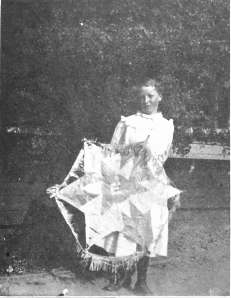
The star kite is probably the best for decoration, as the spacing falls in easier relationships than some of the other forms. In the kite shown in Fig. 116 the covering is applied so as to give a decorative effect, and it showed up splendidly in the air. The colors did not stand out as well as might be expected, however, and while high in the air it was nearly overlooked by the judges. When brought nearer it received the first prize. Another way of combining colors is to make one half one color and the other half another, giving a light and shade effect to each point, Fig. 117.
Fig. 37 shows a pleasing arrangement of spaces. The kite is first covered with the body color, then the bandings are put on, and lastly the spots. A banding around the outside of the stars in the tail is effective and in keeping. Passe-partout is excellent for banding in some places.
The five-pointed star kite, Fig. 38, is neat and artistic. The framework is given to the left.
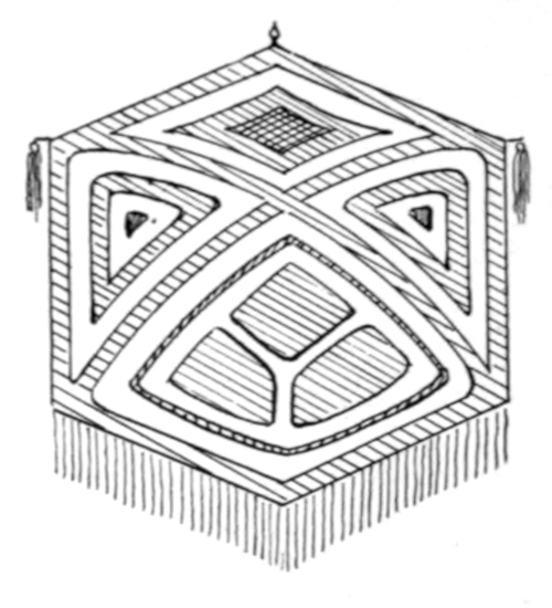
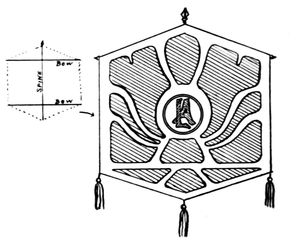
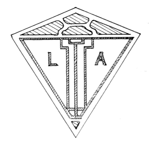
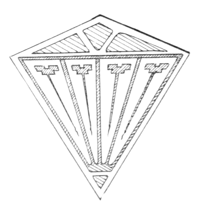
The Six-pointed Star, Fig. 118, has interesting spaces and paths. The wide paths running to the center are divided by passe-partout. The discs at the points are in keeping with the large one at the center.[Pg 62] The main cover was in two tones of grey green. The one spine and two bowed tailless kite gives good opportunity for decoration. Fig. 119 is designed as a banner kite, Fig. 120 a conventionalized bull pup, and Fig. 121 a flower form. The two stick tailless kite is not as easy to space well as some of the others, yet a number of excellently decorated kites of this form have been exhibited. Fig. 122 has a blue body and black paths with gilt over the black. The gilt was put on by hand. Fig. 123 is very similar in design but with light paths between dark. Fig. 124 has a red, white and blue combination with black paths and gilt stripes on the color spaces. In Fig. 125 the radiating lines would be curved in the air.
The Japanese square kite, Fig. 126, is like a canvas, ready for a grotesque figure, a beautiful landscape, or a conventional design, and many of these have been very artistically decorated.
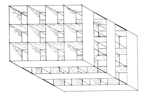
For box-kites with bands as a part of their construction, the banding designs seem more consistent, and so are used more. See Figs. 127-133. Fish, bird, butterfly, boy, man, and clown kites and all forms of representative kites require considerable brush work. Fig. 134 is a beautiful brown kite all decorated with the brush. The school building in the center was painted with water colors. The fish kite, Fig. 135, is all hand work. Fig. 136 is the head for a dragon kite[Pg 63] and should have considerable fierceness. Fig. 137 has the decorative feature in carefully planned lettering which possesses a good space filling quality.
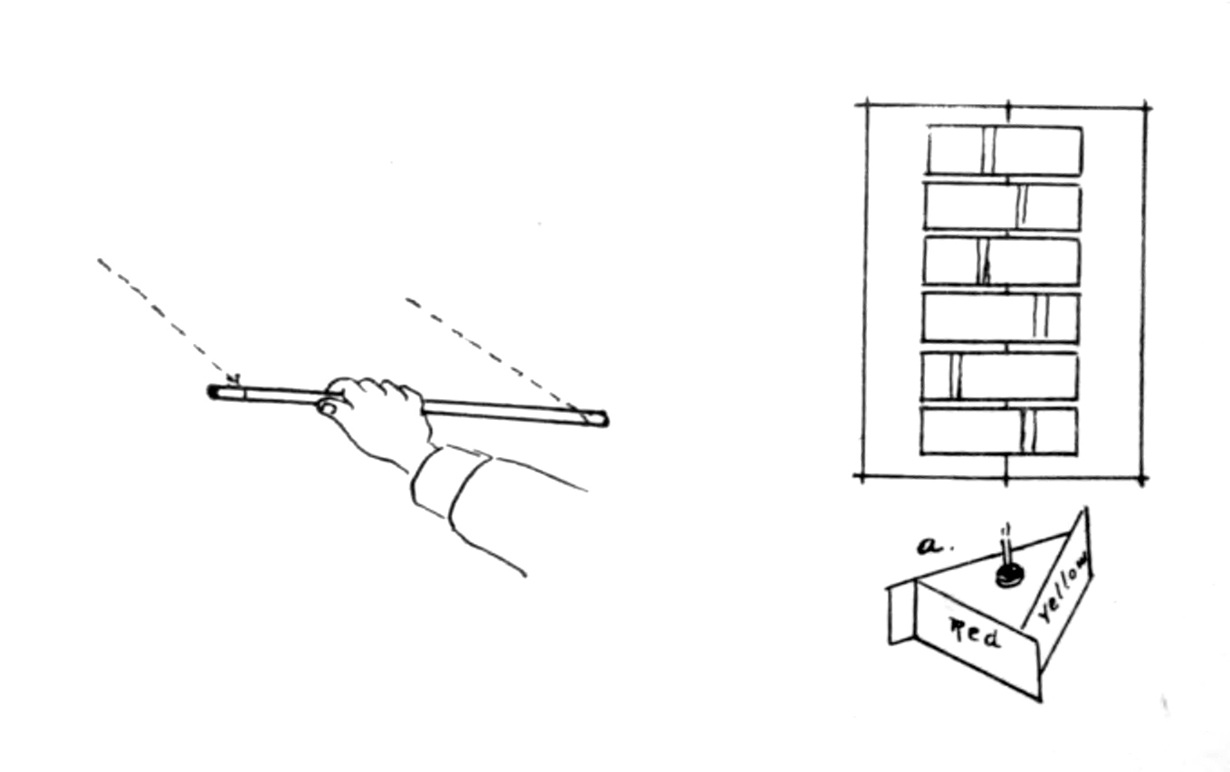
Some very satisfactory results are obtained by using good colors, say blue and black, relieved with gilt. Red and white makes a pleasing combination, also red and black. A circle divided into three parts presents a little problem in color harmony analysis. There are three primary colors: red, yellow, and blue. We may use blue in a color scheme. Combining the other two colors, red and yellow, we get orange. Orange is called the complement of blue, but orange is too strong, and a better color harmony is formed by the addition of some of the third color, the blue to the orange, which will give a brown. Now brown and blue make a better color harmony than orange and blue. So it runs, two primary colors give a secondary, but the colors are more pleasing when subdued with the third color or by the addition of grey or white. Red and olive will need dividing paths of some[Pg 67] strong color, black or white. When gilt is used it must be edged with black or some very dark color or it loses its effectiveness. While orange is too strong for combination with blue, it is good with black. When yellow is used with the purples it should be a modest yellow.
Just as in landscape where the highlights are warm colors, we seek a cool color for shadows, and vice versa, so with color combination we strike across the color circle and choose a warm and cool color for balance. Some of the analogous hues are very pleasing, but unless quite a little variation of color is used, the design soon loses out in the distance. Browns, greens, reds, blues, etc., may be used in their individual color schemes, but the throwing in of some opposite color has a spicing up effect that is helpful. A dark brown, medium brown, a dull yellow, and a light but not brilliant yellow, give a good combination. Some color schemes that are very beautiful for rugs and interior decoration do not carry far enough to be used on a kite. Some very brilliant colors that might shock us close by, are charming when far up in the air.
[Pg 68] But this is not a treatise on color work, and the subject is so great, that we must leave it here. Sometimes striped effects are made with gummed papers similar to passe-partout. The little mirrors mentioned are such as are used on gowns and draperies. They are set in little rims of light brass and with a good allowance of paste may be stuck sufficiently well to any portion of the kite to hold during a tournament. The mirrors might be found at Chinese stores. Whirling devices, to be treated in a following chapter, may also be used for ornamentation. Tassels, streamers, and banners all serve a purpose of artistic makeup when properly used.
All are more or less familiar with the piece of paper with a hole in it that is slipped over the string of a kite high in the air. The wind catches it and whirls it along, until it finally reaches its destination, the kite. Sometimes urgent business demands several communications to the kite, so several pieces of paper are seen whirling at various distances from the boy, making their way, now slowly, now faster, overtaking, falling behind and so on until they fulfill their mission. Such is the usual kite messenger.
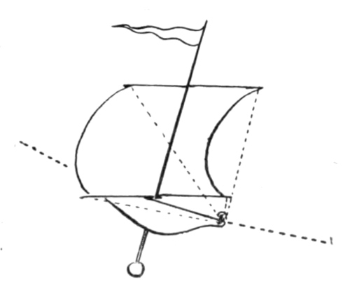
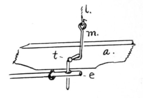
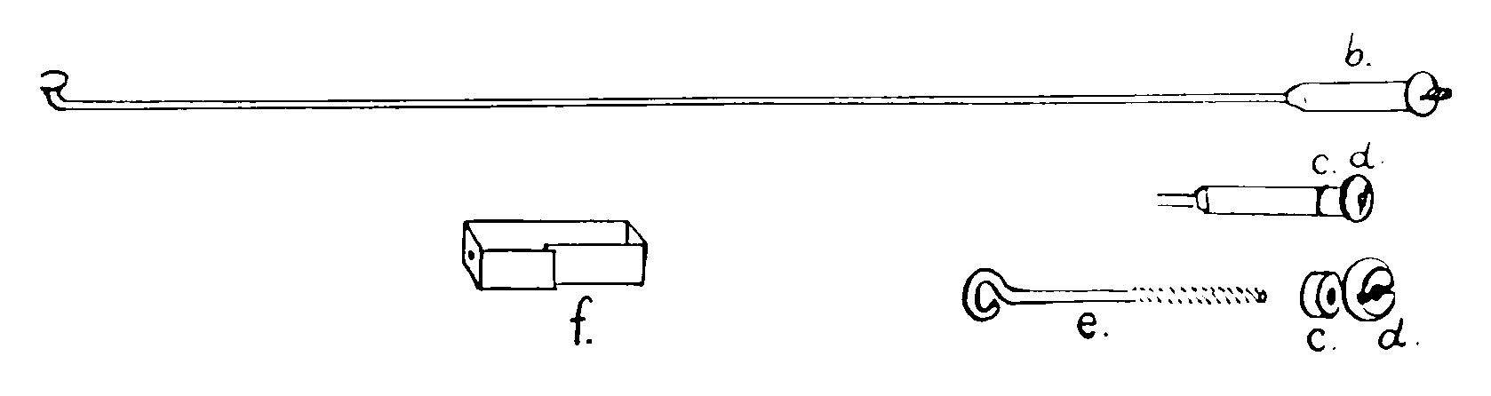
A clever little messenger was described by Nungent in St. Nicholas, for October, 1900. This has been modified and used at a number of kite tournaments. It is in the form of a little yacht, and has a beam on which is attached two pulleys under which the kite line runs, a mast that carries the sail and that also extends downward thru the hull to carry a weight that holds the yacht upright. The mast slants backward a little so as to brace against the pull of the sail. The sail is held up by a string that is attached to an easy trip, and when released the sail drops and the yacht returns down the kite line to the operator by gravity. Fig. 138 shows a complete model with sail up as it appears on the up trip. Fig. 139 shows the various parts: the beam, a, is made of a light wood, ¼” × ½” × 15”, portions are cut away to reduce weight; the mast b, is round, ¼” in diameter at bottom, tapering to a point at the top, is 29½” long, 9” below the beam and 20” above; the mast is lashed to the side of the beam; c and d are yard arms, c being 16” and d 14” long and both about ⅛” to 3/16” thru; c is lashed above the beam, and d is hung by a thread 15” higher up. A thread is run from each end of both yard arms to the top of the metal loop supporting the back pulley wheel. The[Pg 70] threads are for the purpose of preventing twisting of the sail. The sail is of some light soft material that is very pliable in the breeze. Some use silk, others soft cotton, and some paper. I used a Chinese tissue paper sail and found it very satisfactory; it lasted several seasons. The strong way of the paper should be put on up and down. The sail is pasted or sewed to the yard arms. The sail line is a piece of linen thread that is fastened to the middle of the upper yard arm, passing thru a loop made of small wire, u, which is lashed to[Pg 71] the mast, see Fig. 140. The line then passes to the eye of the wire forming the trip on the side of the beam, see Fig. 141. t is a small nail in the side of the beam a; m is a long slim wire nail with an eye bent at the top and two bends at right angles about half way down. A piece of small spring brass wire will do as well as the slim nail. A small round wooden stick, e, not larger than ⅛” at the largest end and about 14” long lies loosely in the screw-eyes, r and s, under the beam. The end of the hook that the sail line is fastened to passes down thru a small hole in the end of the small stick e. A weight, p, is secured to the lower end of the mast to prevent overturning of the yacht, and a piece of light cardboard is used for the hull.
The pulley wheels can be turned on a lathe or small metal ones, especially aluminum can be used. Strips of tin make good frames for the wheels, and are attached to both sides of the beams. If wooden wheels are used, care should be taken to see that the holes are in the center. Wire nails make good axles. The kite line is liable to jump[Pg 72] out the grooves of the wheels, so small screw-eyes placed in the beam just in front and behind each wheel will keep the kite line in place. It may be an advantage to press the eye together some so as to make an elongated hole, Fig. 142. Some care will be necessary to see that the screw-eyes are screwed in just the right distance so as to prevent the string from resting on the screw-eyes instead of the grooved wheels.
The Release. The sail is tripped by the stick, e, being pushed against an obstruction of cardboard fastened perhaps three hundred feet from the kite, see Fig. 143. The reason for placing it away from the kite is that when the weight comes on the kite line, the last part of the trip is very steep; by placing the obstruction some distance from the kite this difficulty is largely overcome.
As a final warning, the sail line should just be tight enough to hold the sail in place while going up and not tight enough to prevent easy tripping when e touches the obstruction disk. Some put on elastic[Pg 73] bands to pull the sail down quickly when it is tripped. The nearer the sail can float out straight behind on the return trip, the less resistance there will be to the breeze. Some even go so far as to have a little rolling up device for the sail. A thread should be attached to the beam and to the little rod e to prevent its falling out on the down trip.
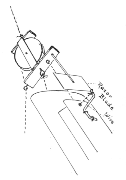
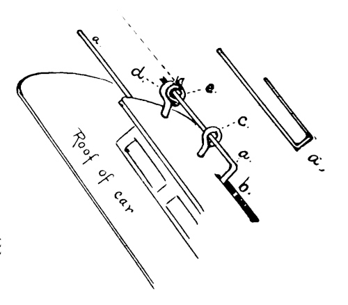
The Chinese and Japanese sometimes have little messengers that are released when a punk burns down so as to burn off a supporting thread. This might be applied to parachutes too. Another good device but which is not self-propelling on the upward trip is the trolley car, Fig. 144. The car is pulled up the kite line to a trip, when it is released and returns by gravity. The pulley block is tied into the kite line, Fig. 145. The line below the block passes thru the car under a little roller on the inside of the car at each end. The car can be made up of any light material, but need not be as light as self propelled devices, the weight being an advantage on the downward run. The line that pulls the car up passes around the grooved pulley, thru the guides in the pulley block and one end goes to the car while the other goes to the operator. A release is necessary, and perhaps a little sharp blade like a safety razor blade will be as effective as any, Fig. 146. In Fig. 147 another trip is shown in which a wire is bent, as at a. This wire passes up thru the upper portion of the roof at b, and passes thru screw-eyes c and d; d is bent forward. The lower portion of the wire as represented is much longer than the upper, and when it touches the pulley block is pushed back, and the shorter portion is pushed back of screw-eye d, which releases the small ring, e, to which the pulling line to the operator is attached, and also sets free the car to run down the kite line. This last is not a difficult attachment and seems a little more scientifically mechanical.
There are other ways of effecting the release. A good pulling kite is necessary, as in the excitement of pulling up the car, more strain is put on the kite than one would realize. If a race is on, a fishing reel would be an advantage. This last messenger is not limited to the street car, but the form might be a locomotive and train, an automobile or an air ship. The latter might have adjustable[Pg 74] wings so as to be open to the breeze on the up trip and so be self propelling as in the yacht, and by releasing that which holds the wings open, they will close up, and the messenger would be ready for the down trip. In the messenger races, it is necessary to measure the string. At a tournament it is necessary to do this beforehand. It is not necessary, but more interesting, to have all the contestants operating at the same time. In case all cannot operate together, each can be timed. Some very comical devices might be devised as messengers, not so much for speed as for amusement. Certain motions might be developed that would add much to the entertainment of all.
Most of the moving devices on kites are operated best by means of windmills. The windmill can be placed back of the kite out of sight. Various movements can be devised such as opening and shutting of eyes and mouth and moving of ears. Feet and hands can be made to dangle without any device. The windmill can also be used for decorative purposes.
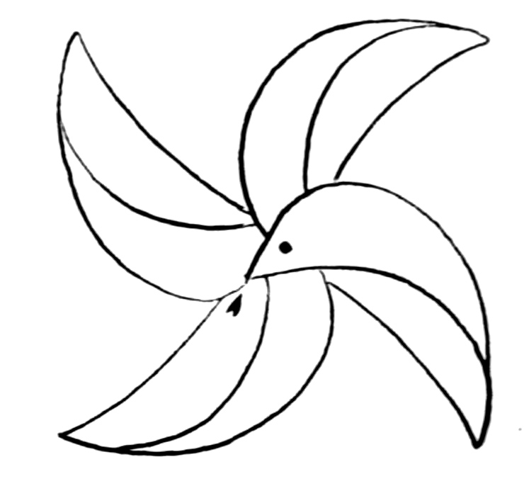
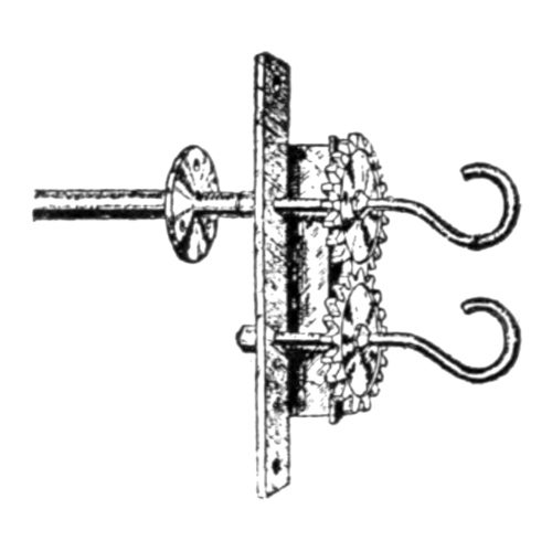
Windmills. There are two general kinds of windmills. Those turning from left to right and vice versa, and those turning fore and back. The last named type is used for eyes that turn. The eyes are set in little rims of some stiff material, a thin piece of bamboo, shaving, or stiff cardboard. Holes are cut in the covering of the kite and these rims are pasted in so as to stand edgewise. These rims prevent the interference of any obstruction to the revolving eyes. The eye may be set in place by means of a wire running thru each side of the rim and thru the eye. The eye has a smaller rim on which two half circles of paper are pasted, see Fig. 148. A little paper wound into a little ball would be made by the Chinese boys, but a glass bead will answer to keep the eye away from the rim of the opening. The two semicircles of paper are on the two halves of the eye. In Fig. 148, a is on the upper half of the front side while the other semicircle, b, is on the lower half of the back. Sometimes little mirrors are pasted to the eyes, as at m, to reflect the light as they spin around, which they certainly do, if nicely set in their places. Some use considerable black on one half and white on the other, giving a blinking effect. This same kind of revolving disk is sometimes used on wires or cord to the outside of the kite, see Fig. 134.
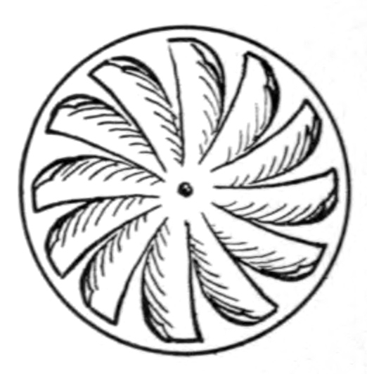
The revolving device, while not as familiar as our little windmills, is more easily secured in position but it is not impossible and in fact is not a very difficult task to fasten the windmills. The windmills can be made of stiff paper, any stiff cover paper will do; they spin[Pg 76] well and are very light. They are usually made of a square piece of paper which is cut on the diagonal nearly to the center, Fig. 149; one of the points of each section is then brought a little past the center and a pin pushed thru, Fig. 150. These little whirligigs can be attached with the pin to the framework of the kite at various places. Larger mills can be made of stiffer paper, as bristol board, but the larger sizes will need more anchorage. The wheel will need an axle of wire and to secure it, a paper, perhaps several, will need to be pasted to the wheel and on the wire to prevent its flopping over. The wheels are made from a circular piece and are slitted from the circumference to near to the center and the sections are curved by drawing the paper over a pencil or similar object until the right curvature is obtained, Fig. 151. All the sections of a wheel are curved the same way but where there are more than one, part should turn to the right and the others to the left. The framework supporting the axle should reach across the opening and there should be a strip on each side as shown in Fig. 152.[Pg 77] If the fans will not remain curved, a wire can be run around the outer edge, thus keeping the fans in place and at the proper angle. Other windmills are made with wooden axles that have little diagonal cuts to receive pieces of thin stiff cardboard as fans. These can usually be purchased, but they can also be made; Fig. 153 has one fan removed. Make a small block and with small saw, make little cuts on the diagonal and set the fans in with glue. Some make little windmills of aluminum, which are similar to the ones made of light cardboard. Windmills can be applied in many ways; for example, they may represent wheels on an automobile kite, Fig. 154, in which the tires are large and the windmill serves as the center of the wheel. When turning around it cannot be seen that the tire is not turning. Another wheel is shown at a in which small slanting fans are attached.
The most difficult part in making the auto kite is to keep it light and in poise. It will readily be seen that the automobile is a triangular box-kite. The hood of the engine should be open at both ends, with string across to represent screen. The hood instead of being a dead weight will have considerable lifting power, being part of a barrel kite. A framework is shown in Fig. 155. The top of the auto might be black or tan, the body red, black, grey, green or brown, the tires light tan, and the moving part of the wheels light yellow.
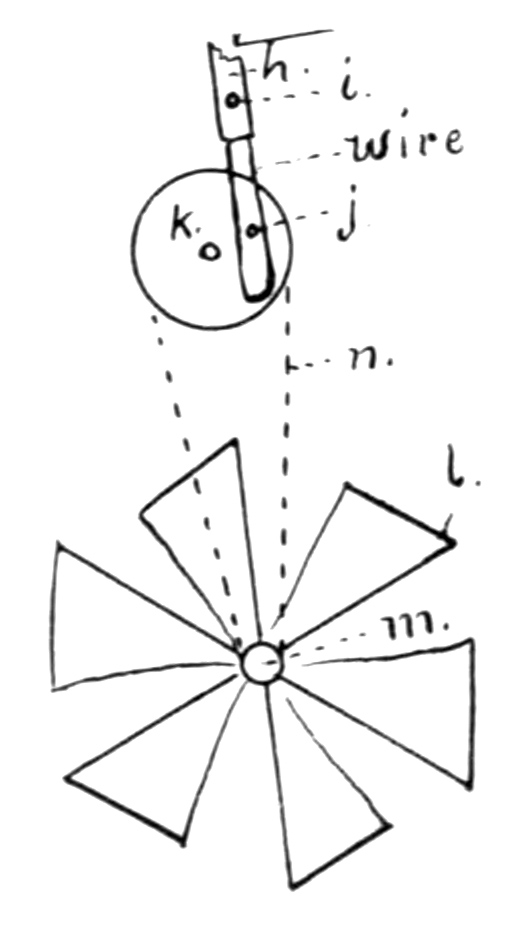
The steamboat kite, Figs. 156 and 157, is another application of the moving wheel but this construction is simpler and the attachment of wheel is better. In this model a part of the wheel is shielded from the breeze, so the uneven pressure causes it to revolve. This is a very feasible and interesting problem. Fig. 158 shows a kite with a wagging head above it. When we understand this device, we should be able to plan many others. The windmill is set in the open part of the kite. Two cross-sticks are used so it is quite easy to attach a vertical piece to the two for support of the aluminum wheel. A little hub has a groove in it that a cord belt runs in, and from that to another grooved wheel to the back of the kite, Fig. 159. A lath nail cut off for a small crank pin, j, is located near the outer edge of this grooved[Pg 80] wheel. A vertical lever, h, with axis at i, has an elongated hole at the lower end that works over the crank-pin and as k revolves, the lever operates from side to side. The hole must be long enough for the crank-pin to reach its highest and lowest point easily. The elongated hole can be effected by extending a wire loop down from the end of the vertical lever to work on the crank-pin. The wire should be lashed with linen thread to the vertical lever and coated over with glue. An object can be used on the upper end, such as a head, a flag, etc. In the same manner, hands and feet may be extended and withdrawn, a turtle might be made to draw in head and feet and many other interesting operations, but in all of these the machinery must work easily, must not lop over against anything else and above all we must remember not to load down our kite with weight or overbalance it with undue leverage at any part of the kite.
Another way of attaching to windmill is to make the wire axle long enough to pass thru and at the back bend into a crank, Fig. 160. The lever h would work direct on this crank as it does on the crank-pin in the device with the second grooved pulley, k, Fig. 159. To make the head go up and down, use a round hole instead of the elongated ones in the vertical shaft. A loop of wire, Fig. 161, should[Pg 81] hold the upper part of the vertical lever in place, and in case of the head bobbing up and down, the lever is not attached at i, Fig. 159, but the loop, Fig. 161, must not be omitted.
Other Devices. But windmills are not the only means of operating moving parts of a kite. An extra line to the ground will give opportunity to the kite flyer to open and shut eyes and mouth and move ears at will. Ears could be made to grow a foot and then be drawn back by light elastic bands. The mouth might open and a red tongue run out, or a pocket in the mouth might be turned inside out, thus releasing a shower of bits of paper, white, colored, gilt, and silver. Let the imagination play for a time, then set the inventive machinery of the brain to work and “watch us grow.”
These devices are usually suspended from the kite line. It is necessary to have enough suspension cords attached to prevent twisting up with the main line. Most of the devices will float out and have some lifting power of their own, but some will require a kite that can sustain some weight, in some cases a pound or more.
Flags and Banners. One of the prettiest attachments is the American flag. This can be attached in two ways: first by means of a vertical stick of some weight, Fig. 162, and second by using the horizontal stick, as in Fig. 163. A pleasing trick is to have the flag folded (do not wind on the stick) and covered, tied loosely with bow-knots that are easily untied, and when the flag is well up, the tripping string is pulled and the flag released. The string of the bow-knot passes down the kite line thru little loops of wire attached to the main line to prevent the tripping string from getting twisted therein. If two are operating, one can stand at a little distance so as not to get the two strings twisted, and thus avoid the wire loops.
[Pg 83] Banners are used sometimes for schools, sometimes for advertising and sometimes for just no particular purpose but the pleasure of doing it. A few banners are shown: Fig. 164 represents the Grand Avenue School, Fig. 165 the Hobart Boulevard School, Fig. 166, Vermont Avenue, and Fig. 167, the Tenth Street School. Fig. 168 shows how the banners are attached.
Wireless Telegraphy. The wireless has a great attraction for most boys. Some attach antennae to the kite, others drop a number[Pg 85] of wires from the kite line, as in Fig. 169. A stick is suspended similar to a banner, except that it requires only two suspension cords; another stick hangs by the wires about ten feet below, and below this the wires come together and a wire follows the kite line to the receiver and to the ground. Caution is here given against the use of a wire kite line. One boy tried this and when the kite lowered in a lull of the breeze the wire crossed the trolley line and in the mix-up the boy became entangled in the line by attempting to get his kite up again, and received quite a shock; but there was no serious results. His instrument and attachments were working splendidly. The winding of the coil is a very good problem for any boy.
Photography. Some boys are interested in photography, and the kite gives opportunity for taking bird’s-eye views. The kodak must rest on a framework and the tripping line be so attached as not to cause the instrument to swing when the shutter is snapped. The tripping can be accommodated by means of the rear suspension cord, Fig. 170. The shutter should trip very easily so as to cause as little swinging as possible. An extension of the lever might be an advantage. The two sticks of the framework should be halved together so as to bring the upper surfaces level. A screw-eye placed in the cross-stick directly below the tripping lever holds the tripping string so that it draws on the camera in line with its own seating on the framework, and causes the minimum amount of swaying. Figs. 171 and 172 were taken on a kite line that was sent up from the Y. M. C. A. building. The speck of white shown on the roof near the[Pg 86] ventilator is the operator. Figs. 173 and 174 were taken by a twelve year old boy and while not as high as the first is a very good start.
Signaling. Signaling can be done by means of a red and white flag, and the code used by the wig wag system, or one similar can be used. Fig. 175 shows the rod on which the two signals are used. Screw-eyes would be better than pulley wheels as there would be no slipping out of the grooves, and there would not be enough friction to be objectionable. The cord operating the two signals should be continuous, passing from the ground to one signal, thru the screw-eye above, then thru the other screw-eye to the second signal and from that back to the ground. The distance from the signal to the screw-eye should be convenient for manipulation by the operator, for while one flag is up the other is down, and this distance corresponds to the pull and relaxation[Pg 87] of the hands of the operator. The signals can be red and white flags, or a device like Fig. 176, in which a full surface of color would always be in view. Sometimes a flag flying directly toward or away from you is not a very large object to see. This last device is made of two good sized cardboard disks, each cut half way thru, Fig. 177, and set at right angles to each other. The red and white is placed there to help in location of the other signals, as to up and would read, red and light, that is r is red or right, while l is left or light. So the same code operates for both. The center black square[Pg 88] down and right and left. The code given is one that we have used somewhat, but not many have mastered it as yet. It can be used for night signalling, as red and white or light, would read r and l too.
We will illustrate with the letter b The code reads L R R L. At night this would be flashed: light, then red, red again, then light. On the kite signal we would run up the light signal, then the red, red again, and then the light. Just so with the wig wag. The wig wag flag would be waved to left then two to the right then one to the left and back again to center. If we were spelling out B O Y, a little pause would be made after B had been signalled, then left, right, or light, red would be signalled, and after a slight pause again, the three reds or three waves of the wig wag flag to the right. A little longer pause between words and then the next word would follow.
[Pg 89]
| A | LL | J | LLRR | S | LRL | 2 | LLLL |
| B | LRRL | K | LRLR | T | L | 3 | RRRL |
| C | RLR | L | LLR | U | RRL | 4 | LLLR |
| D | LLL | M | RLLR | V | RLLL | 5 | RRLL |
| E | RL | N | RR | W | RRLR | 6 | LLRR |
| F | LLLR | O | LR | X | LRLL | 7 | RLLL |
| G | RRLL | P | RLRL | Y | RRR | 8 | LRRR |
| H | RLL | Q | RLRR | Z | LLLL | 9 | RLLR |
| I | R | R | LRR | 1 | RRRR | 0 | LR |
Swings. A swing can be attached to the kite line by six suspension cords, Fig. 178. The boy in overalls is a pleasing figure, Fig. 179. The framework is of light kite sticks and the figure is cut out of light cardboard, but must be reinforced with light sticks across the body to prevent collapse. A stick across back of the arms and two down the legs from this will be sufficient. The sunbonnet baby is good, Fig. 180. The sunbonnet in white and the dress red with pink slippers is effective.
The trapeze performer, Fig. 181, must be placed edgewise in the swing, and the lower stick must be made so it will revolve. The grooved pulley is stationary on the lower rod and should have a good sized grove so as to accommodate two or three turns of the operating line, which should run double to the ground. It is well to have such lines fastened to a stick so that the hand may hold in the center between the two, see Fig. 182. By a twist of the wrist the ends of the stick can be forced to and fro which turns the rod that the performer is on, forward or back. This will suggest other forms of trapeze performers.
Color devices and optical illusions could also be arranged. A color device like Fig. 183 would be an interesting study on the ground, and would be very interesting up a little way on the kite line. Each section, as a, is independent of the others, and the sections should alternate as to directions, the first going to the right, the next to the left and so on. It is as easy to make them go in one direction as the other. A vertical wire reaches from top to bottom of the framework[Pg 91] and beads should be placed between sections, and to the outside at the top and bottom. The colors of a are red, yellow, and blue, but white could take the place of some color, and black of another section. As the sections are not likely to turn with the same rapidity, there should be a constant change of combination of colors.
Light forms that fill out with the breeze can be made of tissue paper and attached to the kite line. Ugly monsters with large mouths and highly colored bodies with heavy lines on them to outline scales are very striking. It is necessary to have these open at both ends or they will be torn open, also it is best to have a light framework about the head to keep that in shape; the rest of the body will usually be taken care of. Long serpents and fish are good for the purpose. If the grotesque does not appeal to one, long and short streamers can be used in abundance. A kite line decorated with pointed streamers of various colors would be very beautiful. Japanese lanterns might be festooned along the line, and to reduce the weight, the bottom could be removed. If kite flying is indulged in at night, fewer lanterns can be used, and these lighted.
Balloons that really go up are always attractive but by thoughtful planning they can be made much more beautiful. A nice white balloon against a blue sky is very pleasing, but most boys like more color. The hot air balloons are made of tissue paper, and consist of an inverted bag with a light piece of reed at the bottom to keep the mouth open. The most successful shape is shown by Fig. 184. This need not be perfectly round on top, but may be pointed, as in Fig. 185. If the balloon is too nearly round like a ball, it is liable to turn over and allow the hot air to escape. If the balloon is too long and slender vertically, it would probably flounder around in the breeze too much. There is not the variety possible in balloons that there is in kites, as no ballast can be attached that is of much service. In some shapes only a very little is necessary to keep them in an upright position, in this case a little ballast will suffice, and a number of shapes can be made with this addition. The ballast should be suspended by strings from the reed at the bottom, see Fig. 186. The ballast may only be a piece of cardboard, but in some cases that little is very necessary.
Some of the boys try models of the dirigible, but usually they get something too large for hot air manipulation. The dirigible is more of a cigar-shaped balloon. Strings run down to a framework that carries the propeller, which is a paper windmill in this case, but it is very difficult to keep these representative parts light enough to be carried by the hot air medium.
In making a balloon like Fig. 184 the covering is made in tapering sections. The pattern given is for a five-foot balloon. The width at the lower end of the section is five inches, three feet farther up fifteen inches, and it comes to a point at the top. The edges of these sections form a long curve, Fig. 187. Five feet would require just a little over two lengths of tissue paper. There are seven sections in the balloon.
Inflation. Two methods are used to fill the balloons. A wire is stretched across the frame of the mouth of the balloon and another at [Pg 93] right angles to it. A ball of excelsior having been soaked in paraffin is attached at the crossing of the two. The ball should be flattened into a disc about two inches in diameter and one inch in thickness.[Pg 94] Holding the balloon up by the top the paraffin disc is lighted with a parlor match. It burns and creates heat that collects in the upper part of the balloon. When it is filled so that it lifts a little and wants to get away it is released carrying up the heat generator with it. The paraffin ball continues to furnish hot air until it burns out. A balloon so equipped will travel several blocks, high up in the air. The paraffin ball is also wound about with a very fine wire which is also used to attach the ball to the wires across the opening of the balloon. It will be seen at once that a good sized opening is necessary and in this design, the reed band is ten inches in diameter.
The other method of filling is by means of a stove pipe furnace or some similar device, but in this case all the heating is done on the ground. A hole is dug in the ground and the stovepipe is banked in as a chimney. A fire is built in the hole and the hot air goes up thru the pipe to the balloon that is suspended over it. If it was not for the stove pipe the blaze would ignite the walls of the balloon. Some quite large balloons have been sent up in this way. A piece of tin or sheet iron is good to make a cover for the hole in the ground so as to prevent the dirt from falling in on the fire. Some use a little oil on the fire, but there should not be too much else the blaze will reach up thru the pipe so far as to burn up the balloon. It is well to have a cord above so as to hold the balloon up and if it is too high to hold with the hand, a pole with a wire on the end of it that could be readily released might be used. As the bag gets inflated it is best to remove the pole and hold to the bottom by the hands.
In pasting the pieces of paper together, there should be about ¼” laps. Care must be observed in the pasting that there are no detached places, places where the paste does not stick well, as the hot air will escape. In the model given, one section was blue, two white, one red, and three white, making seven in all. Sometimes the colors are worked in differently. Half of a section will be one color, and the other half another, and next to each will be placed some contrasting color. Still further breaking up can be done until quite a design is worked out.
It is possible to decorate a plain balloon with surface design, but it must be bold and not over done. An example or two may be helpful,[Pg 95] Figs. 188, 189, 190. Yellow and black, black and red, purple and white, green and white, and many other good combinations can be selected, but two or three colors are better than many. The best grade of tissue paper is very much superior to the cheap, as the tendency of the cheap to split out is very unsatisfactory and there are thin porous spots. The French tissues, so called, are the best, and they come in many shades of good colors.
Parachutes are other forms of balloon. They do not ascend from the ground, but are released up in the air and float downward. Sometimes a current of air will catch one and carry it far up and away. They are made like an umbrella covering, sometimes in sections and again in one piece, Figs. 191 and 192. When made in sections, they are very much like the upper one-third of a balloon. They are made from the size of your hand to beauties that are eight feet across; when made of brilliantly colored paper, they are very interesting. They have a weight suspended underneath to keep them upright in the descent. Parachutes are usually taken up on a kite line and are released well up in the air. The usual method of shaking them off the line is not as good as a definite release by a tripping string from the ground. If large ones are used, one at a time is sufficient and is simple to release. The parachute is tied with a bow-knot to the kite line with the extra string and as this string is pulled the knot comes untied and the parachute is released. When smaller ones are used they can be tied in a series and the lowest down on the string or the highest can be released, then the next, and so on. The same string can be used to tie on a long series.
No matter how small the parachute, it must have its suspension strings and weight. We have tried parachute showers that have only been a partial success, thus far. A bunch of these little parachutes each with its own string tied to the kite line, have been released, but in pulling them up they are so liable to get twisted up, that when released they cling together. If they could be carefully laid in some kind of an apron that would protect them from the breeze, I am sure they might be tumbled out so as to separate without entanglement. It is a very pretty sight to see a large bunch turned loose, each spreading[Pg 96] its tiny night cap to the air as it starts downward. They should be of all colors, and for this purpose the one piece models and one foot in diameter are best. There is always a scramble for the souvenir parachutes when they are released. If one had a rubber stamp outfit, it would be interesting to print something on their cover. Thread would be used for the suspension cords and perhaps a shingle nail for the weight.
Another method of release given elsewhere is sometimes used by the Chinese and Japanese, is effected by using a lighted punk such as used to set off firecrackers; when the punk burns down far enough, it burns off a supporting thread, thus releasing the object held.
Reels are very convenient for most kite flying and quite necessary for high flying where so much string must be let out and wound in again, but an absolute necessity for events where racing is an important feature. Many devices have been used at our tournaments and some have been very clever. A simple and effective reel can be rigged up in a kerosene box. The box is long enough to allow a seat for the kite flyer, a foot brake can be arranged, and an all around satisfactory reel can be made at light expense. Fig. 193 shows such a reel fully equipped. A portion of the top is cut away so as to expose the spool of the reel, it being necessary to see if the line is winding properly, to see if it is nearly off, and to watch for knots or entanglements. A measuring device might also be attached, similar to cyclometers used on bicycles. The end of the box is partially cut away but not the full width of the[Pg 98] box, the portions remaining at the sides preventing the kite line from getting off the ends of the spools. The portion remaining should be a little wider than the thickness of the flanges of the spool. The axle will usually be a broomstick owing to the ease with which it may be obtained and being hardwood, is very satisfactory. A piece of pipe can be used but is hard to drill thru for the pins that hold spool and crank to axle, also the holes that take pins on each side of box to prevent slipping endwise. Iron washers are used on the outside of box and between spool ends and inside of box.
The crank is shown in the drawing and needs no special directions. The pin holding the crank to the axle might be a small bolt with a nut, which adds strength in the prevention of splitting of the end of the wood. A good spool for the reel might be found at a hardware store. Chains come on well made spools that are excellent for reels. These can be fastened to axle by slanting pins; nails will answer if they are not left out too far thru the outside of the flanges of the spool; also pins may be put down thru the drum part of the spool thru the axle. In this case small holes would have to be drilled from opposite sides of the drum.
Other drums can be made similar to Fig. 194. The axle is secured to two wooden disks and the center is built up of other pieces as in Fig. 195, or by wooden rods as in Fig. 196.
A brake is a great convenience when letting out string, as the reel sometimes runs ahead of the kite and so entangles the string; by a little pressure of the foot on the brake, the unwinding ceases. The brake should act directly on the edge of the flange of the spool. The lever of the brake would pass thru the left side of the box, not more than two inches up from the bottom, Fig. 197. In case the spool is too short for the width of the box, wooden blocks can be used to fill in the space, but the opening in the end of the box that the kite line[Pg 99] passes thru must be no wider than the distance between the flanges.
Another axle that has been mentioned is made of pipe. The pipe can be one inch in diameter, and must be drilled for the pins that fasten the spool to it. A three-eighths or five-sixteenths hole can be drilled near the end of the pipe outside the box, in which an iron rod is riveted with its outer end bent at a right angle. The rod forms the crank of the reel. If one has access to a heavy metal vise, the axle and crank can be made of one piece, Fig. 198. If one wishes the reel to run very easily, a washer that fits the axle nicely can be fastened to the side of the box with two screws, Fig. 199. The hole in the wood should be a little larger than the hole in the washer, thus making the washer a bearing for the axle. I have one that turns very freely this way. The wires running down to pegs in the ground, shown in Fig. 193, are for the purpose of anchoring the reel when the pull of the kite is on.
[Pg 100] Thus far the box has been the real support, but other frames can be made as well, Fig. 200. The brake is applied at the rear on this reel, and is operated either by hand or foot. The heavy wires are for anchoring purposes, otherwise the construction may be the same as in Fig. 193.
Another way of securing the metal axle to the wooden spool is as follows: Drill two holes thru the pipe just far enough apart to allow spool to fit between. The holes should be just large enough to allow a 16d or 20d nail to go thru. Cut off the heads of the nails, fit in holes with spool on axle, and with good sized staples fasten pins (nails) to sides of spools, see Fig. 201. For the crank, a ⅜” hole can be drilled at the outer end of axle to receive a ⅜” rod bent at one end to form the handle. The end of the crank that passes thru the axle might be threaded about 1¼” so as to put a nut on each side, see Fig. 202.
A Large Reel. The two general plans given above are for comparatively small reels. Fig. 203 shows a reel that winds in over four feet at a turn. It has but one bearing, being attached to the standard by a large bolt for an axle. It would be well to have a piece of pipe just large enough to allow the bolt to turn freely and just long enough to reach thru the wheel as a bushing, for this is much more like a wheel. The sides or flanges are made of two ply wood, in one-half of the thickness the grain runs one way and the other half at right angles to it, so that it prevents warping and is not liable to spit. There is no real drum, but small wooden rods, or slim bolts, hold the sides together, also apart, and are set about two inches in from the outside circumference. In the drawing, the wheel being 18” in diameter, the bolts or rods are in a circle 14” in diameter. The bolts or rods should be about eight in number. If wood rods, doweling, are used, they would be glued at both ends and no other posts would be necessary, but with the bolts, posts will be needed to prevent the[Pg 101] sides from coming together. Four posts will be sufficient. No crank is necessary on this reel as a handle can be fastened to the side of one of the large discs. A brake can be attached underneath as in the last reel. The axle must be made very rigid in the standard as it has to support all the pull of the reel. This is a first class reel for fast work.
Discs can be obtained at some box factories for seven and ten cents apiece for sizes 15½” and 19½” in diameter, respectively. They are made of two ply wood and make good reels. A good way to get the holes opposite is to clamp the two discs together and bore all the holes thru both at the same time. Others make reels very much like our grandmothers’ yarn reels. Two arms are halved together and short cross-pieces are attached to the ends, Fig. 204. For speed they are made with long arms and take up a good length of string at a single turn.
Another way of building up a reel is shown in Fig. 205. A square block has fans nailed or screwed to each side. The ends of the fans are shaped out to receive the kite line. The end of the square center piece can be rounded so as to pass thru a round hole of the framework, or a hole can be bored thru the square piece and a pipe or rod inserted as with the others. For heavy work where large string pulling kites[Pg 102] are used, geared reels are practical. Fig. 206 shows a picture of a boy and his reel rigged up with a chain drive, utilizing parts of a bicycle. This was devised for speed, but it needs flanges at the ends of the drum. If one wished to put time enough on a reel, he could rig one up out of parts of a bicycle that could be manipulated by the feet. A coaster brake would let out the string and the winding in could be made as swift as any kite would stand. The wheel used for the drum portion would need quite a little modification to prevent the string from jumping off. As the usual frame would not admit of any widening, some additional framework would also be necessary to make it stable enough. If one is going to do much kite flying, it pays to take time to make a good reel, not the last one described necessarily, as that is more for speed, and is not as convenient as a number of others, but a good simple reel is a great satisfaction.
Aeroplane Models are small sized aeroplanes. They may be divided into four classes:
A. Small models of large machines, made for the purposes of construction.
B. Small models of large machines made for the purpose of flying as kites.
C. Gliders.
D. Self-propelling models.
It will be seen at a glance that this chapter should be expanded into a book by itself. Mr. Collins has written an excellent book, “The Second Book of Model Aeroplanes”, on the subject, and I hope the readers of this book will look it up, as it will be worth while. In dealing with the subject in this chapter we can not go into it very deeply and not many plans can be given, but we will try to touch here and there some of the important features of construction.
I have grouped the model aeroplanes into four divisions, but before we proceed it will be well to notice the various classes of large machines. There is the monoplane or one plane type; the biplane or two planes, one above the other; and the multiplanes in which several planes are used. The first two have survived, and form the very large percentage of all that are attempted these days. I should like to make clear that I do not recommend, even discourage, any attempt at gliders large enough to carry the maker, and the aeroplane in which a motor engine is to be placed. There is too much danger connected with them, and our lives and limbs are too precious a gift to be trifled with in such unnecessary ventures. The little models, however, are harmless and yet are very fascinating, even when there is no thought of their embodiment in a large machine.
In group A, where the worker seeks to imitate a large machine in miniature, the joy of the undertaking lies in the processes involving very accurate work and nicety of finish. There is a fascination for young people in the making of things in miniature. The models made[Pg 104] in group A are usually larger than in group D, as the pieces of the framework need a little more material to work to advantage, while in D, the parts must be kept light. Weight is not so much of an item in group A.
The photograph of the Curtis model, Fig. 207, has a clock spring works in it, but it is of no service. This is a very fine piece of work and has been admired by many. Outside of the clock works the model[Pg 105] is all handmade. Little turn buckles for tightening the guy wires were made, as well as the little metal attachments to which the ends of the guy wires are attached. The silk covering was stretched and oiled on the frame.
An equally well made model is shown in Fig. 208. In this monoplane all the curving of ribs and trussing of frame were very accurately done. It will be recognized that this is a very excellent piece of work and the outlines of the planes are very beautiful and well proportioned. The planes are supported at the outer ends by careful adjustment of wires above and below the wings. Notice the two little braces above the center of the framework to which the guy wires are attached. Turn-buckles are used on this model also. The horizontal and vertical planes to the rear of the model, but to the front in the picture, were ideas original with the maker, altho I have seen pictures similar to this since.
Some make up these models in good shape for the purpose of using them as attractions in show windows. Merchants will sometimes give a rental for a good model. Very often when used as a display, an electric motor is installed in them so as to run the propellers.
In group B, the models are made to fly as kites. It is possible to gain much knowledge about the motor driven models by patient study on the aeroplane kite. The kite flying side will not help so much as the gliding. When the aeroplane kite is well up, if the string is allowed considerable slack, the model will glide if well balanced and if the planes are tilted properly. Balance will be necessary both to right and left and fore and aft. It is very interesting to get such a model pulled well up in the air and have a release that will cut the kite line. The punk method is good, only that we would like to have better control of just the time for cutting loose. The punk has this advantage however that not knowing just when it will cut loose you are held in happy suspense, just as you wait for a bite on your fish line.
Another simple releasing device can be used: hooks are placed on the kite at each point of attachment of the bridle, and on the end of each string of the bridle is tied a small ring, which is to be hooked on the hook of the kite. The hooks must bend back and downward and[Pg 107] must be stiff enough not to bend. Of course the kite line will have to be kept quite taut until time for release, when, if the line is slackened suddenly, the rings drop off, thus releasing the kite line. If it glides well some interesting things will develop. There will be swoops and glides, and loop the loops and all sorts of gyrations before it reaches the ground. If one is going to make a model just to fly in the air without the maneuvering, but to look like an aeroplane in the air, it should have the bridle placed so as to cause the kite to stay as near the horizontal as possible. In order to do this, the upper loop of the bridle should be shortened or the lower one lengthened as on a tailless or any other kite. On the tailless kite one can shift the bridle so as to make the kite stay nearly over head, in fact I have had them pass the zenith and dive over to the other side, and that well up in the air. A propeller that is turned by the breeze will help considerably in giving it a realistic touch. Fig. 99 is very good for aeroplane kites. The side wings can be extended and modified, as in Fig. 209, or the cross-pieces can be bowed up, as in Fig. 210. The bridle should be attached only in two places.
A biplane is shown in Fig. 211, one with bowed cross-pieces in Fig. 212, and one with bent up tips on the upper plane in Fig. 213. The folded paper glider made by the children soars excellently; try an aeroplane kite on that plan, Fig. 214. Another modification of Fig. 214 is the bird aeroplane kite, Fig. 215. In this a plane is placed about half way from front to back. The ends of the wings get their curve from the back stick, a piece of heavy reed, and the outline of the bird is also of reed. By drawing the shape on a board the reed can be bent to the shape. The reed should be wet and tacks should be driven at each side to keep the shape until dry. This kite, if well made, should glide for a very long distance.
It would take too much space to go into details with each design, but the drawings I think will be sufficient for most readers who may be planning these models, especially where framework and finished kite are both given.
In group C is to be found the most profitable source of study for the self-propelling model aeroplane. The glider has no motor and no propeller, but is made on the plan of the motored model in the construction and adjustments. The glider is usually made smaller at first, increasing the size to the actual model later. The glider is more useful for study, if it is made heavier in comparison with the motored model. The glider can be thrown by the hand as if it were a spear, Fig. 216, or it can be thrown by a rubber cord, Fig. 217, or by a springy stick, Fig. 218.
All experiments except those intended for adverse conditions, should be made either indoors where there is no wind, or away from buildings far enough to be out of reach of the whirls that are always present near buildings. Heavy paper can be used for planes in some of the experimenting, and even much may be learned by the use of paper models thruout the whole construction, but a little stiffening with small thin strips as reinforcement is better in most cases.
For the model that is thrown like a spear from the hand, wood is used for all parts. The spine can be ¾” × ¾” × 30”, the fore plane ¼” × 2½” in widest part × 8”, and the rear plane ¼” × 4½” in widest part × 20”.[Pg 109] Bevel off the under side of the front edge of both planes. Fasten the planes to the spine with rubber string, rubber bands will do, this will allow easy adjustment back and forth on the spine. There are many experiments that can be tried with this model. Move the foreplane back, try; move back plane foreward, try; move foreplane foreward, try, and so on. This model and all other models are just the opposite of teeter boards. If too much pressure comes at one end, up it goes, if too much at the other, up that end goes, while the same thing applied to the teeter, that end goes down. It then seems clear at the start that we must have balance fore and aft, as well as right and left, with the kite we must balance right and left, but if the up and down does not quite tally we can counteract by adjustment of the bridle, but on gliders and model aeroplanes, there are no bridles. The little ship must go “all by its lonely”.
Another adjustment is possible, and probably will be necessary, and that is tipping of the planes. By the use of little wedges, the front[Pg 110] edges of the planes may be tilted up, and by trial we can decide what we think the best angle, which should not be great. Possibly ¼” might be used under the front edge. It will pay to spend much time in experimentation on these gliders, and it should be carried on until long graceful glides are accomplished.
It will be discovered long before this, that in a very large percentage of cases the arrangement of planes is reversed in model aeroplanes and the large machines. The small planes are placed forward and are used largely as elevating surfaces. A few models have the large plane forward. It will also be noticed in looking over plans of model aeroplanes that a large majority are monoplanes, while in the large machines there are more biplanes.
Warping. No warping of the planes is necessary in the glider that has been discussed, but it is well in the lighter models to have some warping called camber, in the larger planes especially. Another warping is from end to end of the plane, that is, the ends tip upward, never downward. Sometimes models are made with the large plane warped from front to back, and with the small plane bent upward on each side, and again the large plane is sometimes bent in both directions as it is made. The last is more easily done when wire frameworks are used in the self-propelling models. In Fig. 217 the model is made lighter, the spine being a heavy piece of reed with a hook bent on the end and the planes ⅛” or 1/16” veneer wood.
The sling shot device for throwing the glider is made of heavy spring wire, and will require a strong metal vice to bend it in. A forked stick can be used, or one can be cut out with a turning saw. Fig. 218 is quite similar to Fig. 217 in weight, but a square spine ¼” × ⅜” × 18” with planes ⅛” or 1/16” × 2” × 6”. 2” in widest part and the other ⅛” or 1/16” × 4” × 12”. 4” in widest part. The force used to drive this glider is given thru a springy stick of some tough wood, as oak or hickory. The stick should be quite stiff so as to resist more pressure before its release. A little block on the under side of the spine might have a little hole in the back to receive a small nail in the end of the bow stick used to throw the glider, this will prevent the bow stick from slipping off in the throwing process.
[Pg 111] One other glider should be mentioned, and that is one with sheet metal planes, Fig. 219. This has advantages and disadvantages. When it strikes hard against some object, the metal is liable to bend, also if it is thrown violently, and should strike someone on the face or hands it might cut. The metal surfaces can be bent into any shape. All corners should be rounded. Some of these gliders can be thrown long distances if properly adjusted.
After working awhile with gliders, we can try model aeroplanes that are suited for the instalment of motors later. Everything must be made as light and strong as possible. All kinds of ribbed surfaces, keels, and light wire braced frameworks, are utilized. Everything that would be used in a self-propelling model, except the propeller and motor.
Make the planes movable so they may be balanced as to pressure, by moving them back and forth, flex more, flex less, tilt more, tilt less, until you get a good glider out of it, then attach your motor and propeller. Some may think best to put motor and propeller on, and do all the experimenting, but it takes time to make a good propeller, and the fewer jams it has the better, so it is better to do some experimenting with the model before the propeller is added. The motor will make practically no difference in the balance, so there would be no advantage of putting it on for experiments in gliding.
We are now ready for some attempts on the self-propelling models.
Self-propelling air devices must be of the lightest possible weight and yet they must have strength. There will be no attempt to give a great variety of model aeroplanes; but a few can be discussed, perhaps three or four. The first is a little practice model that has been of great service to me, both for study and for instruction to others. It is small and will not fly far. I can wind it up and turn it loose in a schoolroom. It hits rather hard sometimes but nothing has happened to it beyond a broken propeller, and the rubber bands that are used to tie the planes to the spine have been broken.
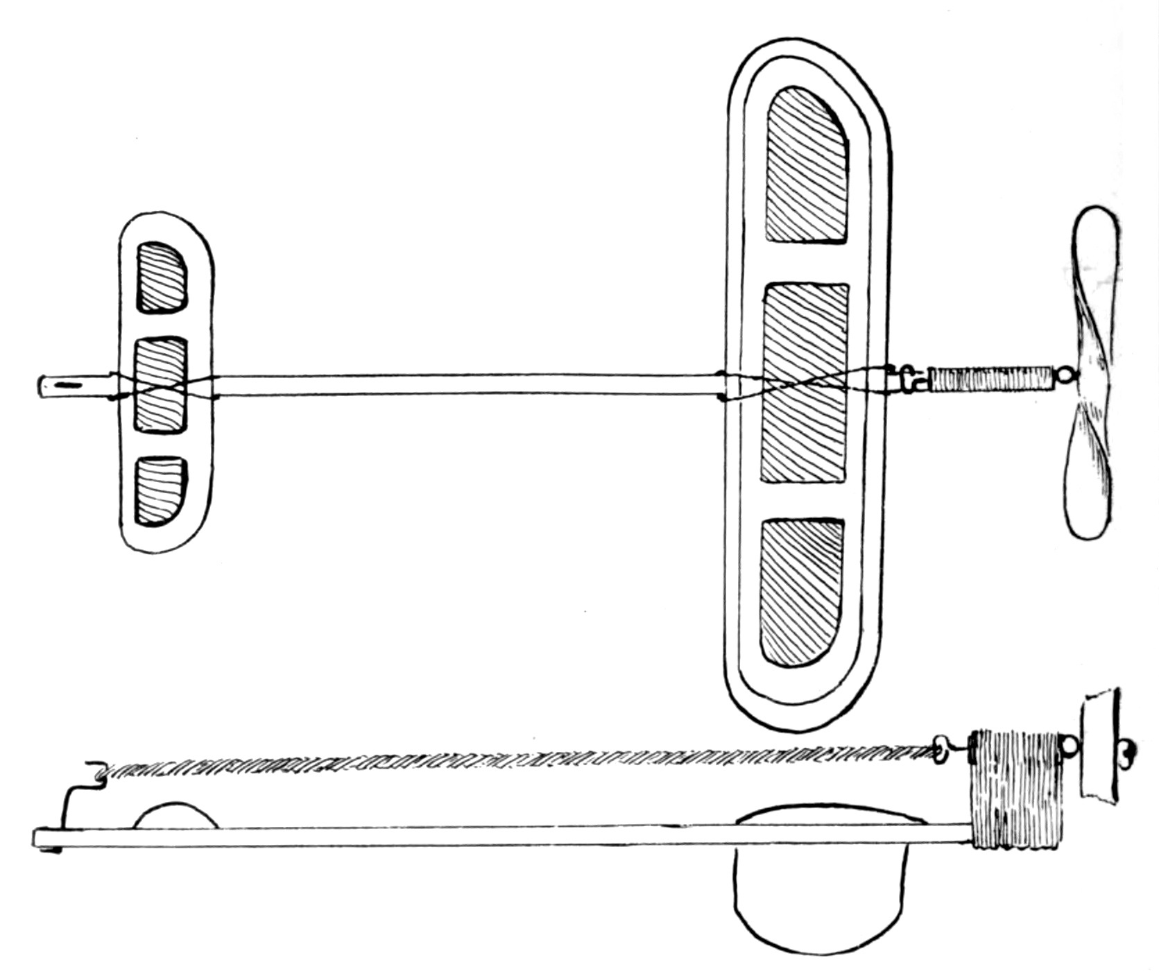
Fig. 220. ↑
In Fig. 220 the model is shown in two views, the plan and side elevation. The planes are made of 1/16” birch veneer, but other woods will do. The small fore plane is bent at quite a sharp angle and was[Pg 113] shaped as shown in Fig. 221. Steam the plane thoroly over the teakettle and place it under pressure until dry and it will remain so bent. The plane is also tilted up a little by means of a small wedge.
The spine is made of spruce and is ¼” × ¼” × 12”. The large plane has about ⅛” camber and is bent as shown in Fig. 222. Lay a strip as thick as the desired camber on a board that you can nail brads into. Steam the veneer for the plane and lay in the ⅛” strip in this case about one-third the distance back from the front edge, bend down until the edge touches the board underneath the strip and drive brads in slanting so as to hold it down. The brads can be bent down a little after they are driven in. By using brads on both sides the veneer can be held down until dry. The outline can be cut away before or after the bending. The decoration of course is not essential, but it is interesting to beautify it a little. The anchor block for the propeller shaft is of wood ¼” × 1” × 1” and is glued and nailed with brads to the rear end of the spine. A piece of tin ⅜” wide is bent about the top of the anchor block, f, Fig. 223. The hole in the wood should be larger than the propeller shaft while the hole in the tin should make a good fit. In this way the bearing is on the tin instead of the wood, and reduces the friction to a minimum. After the tin is on, the block should be wound with linen thread and coated with glue or shellac.
The propeller shaft is made from a bicycle spoke, Fig. 223; two of these can be purchased for a nickel. The long nut,[Pg 114] shown at b, is cut with a metal saw in two places, giving small nuts c and d; c is used on the inside and d on the outside of the propeller. The spoke is then cut off long enough to pass thru the propeller, a glass bead as a washer, and the anchor block, with room for a good hook on the end for the attachment of the rubber motor. The propeller will be discussed further in the next chapter; the only thing to be mentioned here is the size of the blank from which it is made, which is ½” × 1” × 4”. Another piece of the spoke is bent as in Fig. 224, and is inserted in the fore end of the spine and bent still further into shape like Fig. 225. This gives the other anchor hook for the rubber motor. One other piece is the small keel shown in the side view. A groove is made in the under side of the spine and the keel set in with glue.
I am using four rounds of 1/16” rubber string for the motor. That makes eight strands. Six do very well. This is a very useful little model but it will not fly over fifty feet, or mine has not, but the fact that it does not fly far, gives you opportunity to study its start, its landing, and its flight. The long distance models are out of observation range so soon that we miss the chance to diagnose their crazy symptoms, if they have any, and most of them have some.
At the beginning of model aeroplane making, everyone seemed to try to see how much surface could be exposed in the planes, now the best models are those with as narrow planes as it is possible to use and still support the air craft. The reason is obvious—there is so much skin friction on broad surfaces. At the beginning, many were inclined to scoff at the rubber band motor, but since flights have been made considerably over a half mile, with this same power, it seems good enough for anybody. Most of the long distance flyers have long framework so as to accommodate long strands of rubber, which allow much increase in the winding up of the motor.
[Pg 115]
A Good Model. A simple and effective model is shown in Fig. 226. Lay out a light framework, as shown in Fig. 227. It is the combination of a tailless kite and a triangular box-kite. Three long sticks, a, b, c, are used for the triangular portion and three cross-sticks, d, e, f, are for the wing supports. A vertical post, g, about ¼” × ⅜” × 8” is used in the center of the rear (the wide part), to stiffen the frame and give an anchorage for the propeller shaft. Four light braces, h, i, j, and k, make it possible to use lighter material than one would suspect for the entire framework. In a model 3’ long, a, b, and c, need not be larger than 3/16” square, but there must be no split or uneven places in a stick so small. The braces ⅛” × 3/16” would be plenty large. The two upper pieces, b, c, should be flattened on the inside of the front end so as to make them join together, terminating in a point. The lower spine, a, should be flattened on the upper side for the same reason. All three should be glued and lashed together with linen thread. A triangular block, l, should be placed about 4” back from the front end with a strong cup-hook screwed in the side toward the rear, on which the ring of the rubber motor is attached. The block, l, must be well secured to the triangular framework with glue and thread. The cross-piece, d, is 30” long and is bowed upward as is shown by Fig. 228. Piece e is 24” long, 5” in front of d, and both are 3/16” × ¼”. ⅛” × 3/16” will be heavy enough for f, and this should be bowed much more than d, and e. It will be necessary to steam this piece a little. Chinese rice[Pg 116] tissue will be good for covering. Cover the underside of the two planes, and the underside of the triangular framework which is similar to the hull of a boat, and acts as a keel. Test out well as a glider. Put more and less curve to bows, and experiment for poise of model. A small piece of tin on each side of the support will give a good bearing for the propeller shaft. The hole in the wood should be a trifle larger than the shaft. String is run from both ends of d and e to the front end of the framework but is not attached to f.
When long models are made with single spine, they need some simple wire supports to prevent springing up or down, and from left to right. Fig. 229 is 4’ long and the spine is only ¼” × ¼” at the small end ¼” × ⅜” at the larger end. A little 1/16” oak veneer cut in strips 3/16” wide would be very serviceable for the purpose of support in trussing the long spine. It should stand 2” above and below the spine, and the same amount for the right and left brace, Fig. 230. The wires for these should extend about a foot on each side of these posts, and be attached to the spine with little tin anchors, as shown in Fig. 230, a.
[Pg 117] The propeller shaft bearing is of metal and is lashed to the cross-piece, called the base, Fig. 231. It is not necessary to have two points of bearing for the shaft. The metal is about 1/16” × ¼” × 1”, bent as in Fig. 232, and lashed to the under side of the base. The planes are similar to those in the next model. 1” × 1½” × 7½” propeller blanks are used. Try about fourteen strands of 1/16” string rubber for each motor, seven rounds.
My favorite model aeroplane is shown in Fig. 233. It had made some very pretty flights when it took a notion to glide into a young man’s bicycle as he was riding by. Well, there was no improvement on the aeroplane when the chain and spokes of the bicycle were thru with it.
The framework is light and is spread well at the rear. The two spines are 3/16” × ¼” × 33” and they come together at the forward end,[Pg 118] the vertical section being ¼”. Nine inches back from the front end is a cross-piece that is just under ⅛” in thickness, ¼” wide and 2½” long. The cross-piece is on the upper side of the spines, and is fastened by a small ¼” brad, is lashed with thread and coated with glue or shellac. The other cross-piece is 1” forward from the rear end, is of the same dimensions in cross-section as the forward piece, but is 8” long and is secured in the same manner as the other, see Fig. 234. The framework is further stiffened by two fine wires that run diagonally from the ends of one cross-piece to the ends of the other. They are secured to the inside vertical face of the spines by means of small pieces of tin that have two small holes, one at each end, the one receives a ¼” brad that is driven into the spine, while the wire is attached to the other hole. The little pieces of tin are about 3/16” × ½” and are lashed to the spine in addition to the fastening by the small brad. This kind of fastening prevents slipping, also the cutting into the wood, either of which would destroy the efficiency of the wire. In order to increase the tension of the wire, a small turn-buckle is inserted, Fig. 235.
The bearings for the propeller shafts are lashed to the outside face of the rear end of each spine, Fig. 236. The bearing is a piece of brass 1/16” × ¼” × 1”, and is bent to a right angle at the middle. A small hole[Pg 119] is drilled for a brad into the side of the spine and the other hole is drilled to receive the propeller shaft, which is 1/16” steel wire. The shaft is bent into a hook after it passes thru the bearing. To prevent the rubber of the motor from touching the steel wire, which is injurious to the rubber, a small rubber hose is slipped over the hook. In this model, the propellers are pieces of veneer steamed and pressed into the spiral shape. The propeller shaft then is bent around the center of the propeller, has two little washers between this and the bearing, after which comes the covered hook, see Fig. 237. A piece of tin ½” wide and 1¼” long is folded about the propeller before the shaft is bent around. The shaft is soldered to the tin, the tin being secured by two small brads and shellac. A small tin rudder with a small fold in its upper portion may be slipped over the back cross-piece, Fig. 238. The fore plane is made of very thin spruce, shaped like Fig. 239, and is bent up almost like a butterfly’s wings, Fig. 240. The wood is less than 1/16” thick. A double hook as anchors for the double motors, is bent and secured about the fore end of the framework. The hooks are covered with the rubber hose, the same as the propeller shaft, Fig. 241.
The large plane is 4½” in the widest place and is 20” long. It is the shape of Fig. 242 in outline, the straight side being to the rear. The outline of the plane is a steel or brass spring wire 1/16” diameter and is[Pg 120] spliced at the center of the long sides, being soldered at this point. The ends of the wire lap over an inch or more. There are but two ribs which are 5½” from the outer ends. The ribs have a slight curve upward, most of it being near the free edge of the plane, Fig. 243. The ends of the ribs are bent at a right angle and are soldered to the outside framework of wire. The cover of the plane is made of prepared silk and is made ¼” larger all around than the size of the outline of the wire frame. A ¼” hem is then turned which gives strength to the edge. The cover is now over cast with needle and thread to the framework, stretching fairly tight.
The framework of the large plane is not secured directly to the wooden framework of the model, but is soldered to wire loops that in turn lie flat on top of the spines of the frame, Fig. 242, a, a. This gives opportunity to tie with string so as to try out the model. If it is too far forward, it can be slipped back and vice versa; when the correct position is located, it is permanently wired to the wooden framework. The fore plane is attached by means of rubber string. This is known as the Mann monoplane, and is a commercial product.
The propellers will be further discussed in the next chapter.
There are four kinds of propellers:
1. Propellers carved out of solid and laminated blocks.
2. Metal propellers with curved or twisted surfaces.
3. Built up propellers. In this type a small block is used as a hub, and the wood or metal fans are projected out from this. The fans are attached on the diagonal.
4. Propellers made of pressed wood veneer. These are excellent, but require more skill and more apparatus to make.
The carved out propeller is the one most generally used and is not only a good exercise in modeling with a knife, but is a good serviceable kind. There are a number of types of propellers, named mostly by men who have designed them. For simplicity in laying out and carving, I like the Langley type. A rectangle is made of wood, say ¾” × 1½” × 6”. Fig. 244. Draw the diagonals, as in Fig. 245. With a radius of ¼”, and center at the intersection of the diagonals, draw a half-inch circle. Connect the diagonal lines and the circumference of the circle, as in Fig. 246, and cut down to the outline as it now appears. The blank is now as shown in[Pg 122] Fig. 247. We will now take off two big slices, not all in one cut, but in several. Fig. 248 has the dotted lines showing the depth to be cut, and Fig. 249 shows these same parts cut away. Now cut away x and x until the blade is curved back to edges z and z. The cut away portions will be as in Fig. 250. Cut the opposite side the same way, and cut away the back corners a little, giving the result as shown in Fig. 251. Sandpaper well and shellac. Drill hole carefully for the propeller shaft.
The principal objection to the metal propeller is the bending that is liable to occur when the model lights, unless there are lighting devices underneath, and they all add weight. The hub propellers may have metal or hardwood veneers for fans. The hub may be round or square; see Figs. 252 and 253. Very good propellers may be made in this way. Extra curvature of the outer ends of the fans is possible, Fig. 254.
The veneer propeller must be steamed and pressed. This is by far the most difficult to make. The 1/16” hardwood veneer is the best. The propeller is not reinforced to make up for the extra thickness of the carved propeller, but is of uniform thickness thruout. The veneer is first cut to shape in outline and then is steamed and twisted to shape. Fig. 255 shows a pattern for a propeller blade. The veneer should be steamed or soaked in hot water until the wood is very pliable and soft. A form should be ready so as to get both wings with equal twist from the central portion. I will suggest one, others can be devised. A clamp is necessary for the center, which may be made as follows: take a one-inch piece of wood about 1¼” wide and any length. Set it up[Pg 123] edgewise. Make a cut 1/16” deep and one inch long across the upper edge, Fig. 256, and screw a small piece over top as a clamp. After thoroly steaming the propeller blade until it is very pliable, insert it into the clamp at the center and twist from the straight side, one fan up, the other down. It is not easy to get the two sides just alike, so I recommend the bending of one side at a time, and when that is dry, remove, and reverse the ends, being sure to keep the straight edge to the front, or the same as before. To be accurate, there must be a guide block to bend to. For a nine-inch propeller, a block like Fig. 257 would be about right. Place guide in position, press blank down to the oblique surface and secure there until dry. Repeat for the other end. It will be seen that the guide block and clamp are both secured to a board for a base; they may be secured to a table or bench-top. A clamp might be devised also that would hold the propeller in a vertical position with guide blocks on either side of center so as to bend and secure both ends at the same time.
Another way to bend propellers is to clamp the center of the blank in a vertical position, and with two clamps made by sawing into[Pg 124] the ends of two pieces of wood, Fig. 258, a cut wide enough to take the thickness of the blank, and deep enough for the width, bend one blade forward and the other back, Fig. 259. The small clamps on the propeller blades should be placed at equal distances from the center, and should be given an equal amount of twist. The small clamps on the blades will not be forced over until they touch the base, so blocks of equal size should be used as stops in the operation of twisting. The clamps should be secured in the last position by means of cord to the base until the propeller is dry.
Still another way to attain the twist in veneer propellers, would be to have two blocks gouged out to the proper shape, one just fitting in the other. After the propeller is shaped in outline and steamed, it is placed between the two blocks, which are in turn clamped firmly together until propeller is dry.
Motors. Quite a number of devices have been tried, but the rubber string is by far the most efficient power yet discovered. Rubber has a great deal more power than an equal weight of steel in all ways that steel has been tried. The power of the rubber motor is dependent on the unwinding of the strands of rubber after having been wound up. The longer this unwinding may be delayed the further the little air[Pg 125] craft may be propelled, providing there is force enough expended at any time to give the necessary momentum to the propeller. A long motor has more revolutions than a short one. Hence some advocate a long spined frame to the model aeroplane. Others prefer to cut the frame a little shorter and give great pitch to the propeller which demands more energy at a given time, hence heavier strands, or more strands of the smaller rubber string. With the greater pitch propellers, the model is propelled faster and so may cover as great or greater distance than one with a motor that gives more revolutions in unwinding, but it is possible to revolve so fast as not to propel at all. Many use the 1/16” square rubber string, others the ⅛” while many use ribbon rubber, say 1/32” to 1/16” thick by 3/16”. ¼” and 5/16” wide. For small models, rubber bands can be looped together.
Gears. Small, light weight gears can be made or bought. They are attached to propeller shafts and are geared back different pitches. Some one to two, others one to three, while some gears are one to one. It might seem that one to one is added friction and no gain in winding, but a hook is attached to each gear wheel which allows two rubber motors instead of one, and allows longer unwinding. If the rubber strands are divided they wind up many more turns than when combined in one bunch. If eight strands are twisted together you cannot turn as many times as with four strands. Fig. 260 shows a one to one gear and its connections, and Fig. 261 a gear with a greater ratio.
A gear of one to one might be placed at the opposite end of the framework from the propeller, thus extending the number of revolutions in that manner, the second rope or motor extending back and below the first, Fig. 262.
Winding Devices. It is tiresome to wind up the rubber motors by hand, so mechanical winding devices have been made. A drill with a hook in the place of a drill-bit is quite satisfactory. It is best to have a ring on the rubber motor where it is attached to the anchoring hook. This ring can be hooked on the hook of the drill. This winds but one at a time, so they[Pg 126] should be changed about in the winding process, first on one and then on the other back and forth, until tight enough. A very good winder can be made of a revolving egg-beater. The egg-beating part is cut off, leaving two shafts instead of one. If there is a hook on each, both motors can be wound at once and as they should be wound in opposite directions, the device works all right.
All of the work of construction and flying of kites is interesting and profitable for development yet there is opportunity for furthering this interest by bringing about yearly tournaments for the exhibition of the many efforts in construction and design that are undertaken. The tournaments have a further usefulness in the bringing of our schools together in a great outdoor social event. The spirit of such an event is excellent and the day is a joyful one to the children and parents. Thousands attend these yearly gatherings.
The Director. It is necessary for a good tournament that some interested and competent person take general charge of the whole affair and not leave the planning and arranging to others. Helpers are necessary at the tournament, but preparation should be directed by some one person. In so doing, we do not overlook the helpful cooperation of the principals at the various schools, but seek to interest them as to possibilities of undertakings by their children. Instructions should be sent out from time to time as to new things to be constructed and three or four weeks before the tournament, quite complete instructions regarding the different events that may be entered, and rules pertaining to each should be posted in each school.
It is well to organize a little in the schools that are interested. Some boy may be recognized as a leader and a good kite maker. He can round up the team, get the boys interested and encourage them to enter events not yet taken so as to cover as many events as possible and fewer in the same. The preparation for the tournament gives a great opportunity to the teachers and principals to get in touch with boys. Many boys have come to know their teachers with just such an introduction, and it has been the means of starting a good many boys to work in the schoolrooms on their studies. Some boys seem to get out of gear with their schoolroom environment and need a little touch of play, a tramp, or some form of sport to get them back to their real school life. This kind of undertaking is one of the great opportunities for the teacher to get near to the boys. Some teachers are enthusiastic enough to send out for a good sized bundle of sticks and have some one retail them out to the boys at cost. The boys appreciate a little[Pg 128] effort of this kind even if there is no prospect of a tournament. A discussion of design in the drawing work will also be a practical departure from the regular work, and will again arouse the lazy boy to do his best. Now if the teacher will take some interest in the making, even if she doesn’t know very much about it, and especially in the flying of the kites, she will be progressing, and there are but few teachers who cannot learn a good deal about kite making and flying, if they are willing to try.
The manual training teacher and the shop are very able assistants to the kite construction projects. In some schools, a week some time previous to the tournament is allowed for the special construction of kites in the shop. The boys will waste valuable lumber if allowed to rip up thin boards, so it will pay to encourage the buying of spruce sticks. There is much adjustment in attaching string and covering, and putting on of the bridle; as much as possible of this should be reserved for home work, but some might be done at school.
Suitable Location. But the work at the school is not a tournament altho an important factor of it. The director, we will call the manager of the tournament, must find a suitable location. It must be open to the breeze, free from wires, accessible by street car service, a little to one side so people will have to go a little out of their way to see it, hoodlums don’t usually care so much for beautiful things, especially if it is some trouble to go to it, and it should be large enough to accommodate a great many kites without getting into too close quarters. Kites are liable to dive around somewhat, so if they are not too thick, there is more chance to get the kite straightened up before getting entangled in other kite lines. Now that there are so many kinds of kites, it is necessary to locate the kinds on the field. The kites are divided into groups when the list of events is sent out, and these groups are placed in different locations on the field. We will suppose the following group is to be located.
Group D.
Measured Events.
27. Highest Flyer—Single.
28. Highest Flyer—Tandem.
29. Highest flight in five minutes, etc.
[Pg 129] On the ground, separated from the others, would be a bulletin board that is fastened to a post and this is set in the ground. The post is about nine feet long, and the bulletin board is nailed to it, the lower edge being about one foot down on the post. If the post is set eighteen inches in the ground there would be six and a half feet up to the lower edge of bulletin. The announcements can be printed with chalk. They stand out and can be read across the field, see Fig. 263. The tournament is always on a Saturday afternoon, so the bulletins are set Saturday morning.
If there is no space fenced off for aeroplane model flying, and for the races, a few posts should be set and two wires about No. 9 run around an enclosure. Make it an enclosure, for if you don’t it will be impossible to keep the spectators back. We tried a V-shaped fence, but it was useless; with an enclosure and two or three policemen about, it is possible to keep the crowd out.
Judges. Settle on your judges at least two weeks ahead of the tournament. It will assist in arousing interest in the schools with which they are connected. Principals and manual training teachers should be available and serviceable. It is not necessary to be a kite maker to be able to judge a kite. About three judges to a group is good, then if one fails to appear you still have two. Try to start at the appointed time and urge your judges to be there on time. Caution the pupils about putting their kites up before the time, as they are so liable to accident if played with beforehand.
Save a place of honor for your superintendents. They may be asked to award prize badges, or to select the prettiest kite in the air, and the most ingenious device, the best made model or the best invention; not all of these but something of this kind. Don’t forget to use them in some place. Get the promise of two, three, or four policemen, a few days ahead. The presence of a few good officers helps in curbing desires for destruction among a few. Kites are liable to accident, so if you[Pg 130] can have a kite hospital where the boys can get a little paper and paste, string or stick, it will sometimes heal quite a disappointment.
An information bureau is a good feature. Have a bulletin showing its location. The judges as well as the children and parents would be glad of some help of this kind. Official badges are given to the judges, director, superintendents of schools, information and badges, and helpers. The badges are given out to the officers at the information bureau. A small stand at some prominent location in the field would be of service for the giving of the prize badges to the winning contestants. Each winner receives a slip, Fig. 264, from one of the judges of his group, giving his name, school, the first or second prize and event, the judge keeping a duplicate record on a mimeographed sheet that is mounted on a piece of cardboard, Fig. 265. The pupil takes the slip to the awarding stand and hands it to the judges. The judges turn in their records, and the director fills out a small diploma of recognition, Fig. 266, and sends it to the school from which the boy has entered. It may be a girl; we[Pg 133] have had a number of winners among the girls. These slips and record sheets for the judges will be some of the work for the director before the tournament. Each pupil who wins in any event receives an appropriate badge, Fig. 267.
If it is convenient, it is always well to have two transits give the actual heights of high flyers. Some simple ones might be made, but there are often students who would like the opportunity to do some work of the kind for practice. It is well to send out a printed list of the winners to all the schools after the tournament. It might be written as follows
25. Highest Flyer—Tandem.
First. Albert Johnson, 24 St. School.
Second. Victor Wagoner, Washington St. School.
In sending out notices before and after, request the principals to place them in a conspicuous place for the boys to see. The principal’s office is not a good place, for some will not go to the office to study them, these boys may be just as interested but they don’t care to have us know it. If the material is where the boys can see it easily they sometimes get interested unawares to themselves. All plans should be placed in an open place.
The newspapers are glad to publish notices and pictures, and some will even print plans of work free. They are very persistent in getting reports of the tournament, so the judges should be careful in recording each event. The reporters will be on the ground if they have knowledge of its whereabouts.
Ice cream and sandwich wagons are liable to get in the way, so it is best to restrict them to the margin of the crowd. They should not be allowed to come inside any of the locations for the events.
All string that is to be used in races of any kind should be measured beforehand. It is best for the director to take charge of the string until time for the event, or until he can turn it over to the judges in charge of that group. Boys are liable to make a mistake in getting their string too short, so it must be measured. I place a couple of nails one hundred feet apart in the rail of the board fence, the boys wind about that until they have the required length, and by counting the string I can soon see if it is correct. If the string is given back to the boy, there is a temptation to take out some. There is no disadvantage in letting out the string from a stick in the races, if there is a reel to attach it to when it comes to the winding in.
Announcements should be sent out a week ahead of the tournament that the string will be measured such and such afternoons, perhaps two days before the tournament. It is not best to leave it until just the day before, as the director should be as free as possible from such work at such time in order to give full attention to rounding up of details that are sure to accumulate toward the last of the preparations.
Quarter Mile Dash. The race consists of the letting out and winding in of a kite on one quarter mile of string. The boys set their reels ready for the best speed and they group themselves quite close together, but far enough apart to prevent mix-ups, and at the proper time are handed their string that has been measured and labeled which they attach to kite. Each boy in the race is allowed one helper and the kite may be held by the helper a hundred feet away, ready to toss it in[Pg 135] the air at the sign for starting. When all is ready, the one in charge of the group calls “ready! go!” The kites are tossed up and are given the string as fast as it will be taken. The boy with a steady head will sometimes stop playing out and work his kite up a little to get more breeze. If there is plenty of breeze, they are fed all the string as fast as it is pulled out. If a kite drops it may be worked up again, but it must go to the end of the quarter mile and back. A time keeper is placed by each contestant, and officers are needed to keep back the onlookers. As soon as all the string is out the boy slips the loop on the end of his string over a hook on the reel and winds in as fast as he can turn. The kite mounts up in the air and is pulled with great violence toward the reel. If a string breaks, the time keeper stops the winding until the kite is again attached. No allowance is made for mishaps. The kite that is jerked down into the reel first is winner, and the owner is usually a pretty warm boy. The helper can take turns in winding.
Other races should be similarly conducted. We have had races in the construction of a tailless kite, including the lashing and stringing of framework and covering, attaching of bridle and the kite must fly. In all pulling contests, spring scales are used. In the light weights, the twenty-five pound scales are best, but the fifty pound is more serviceable for all around purposes. For very heavy pulling, large ice scales might be borrowed for the day from some hardware man.
To measure the pull of a kite, the string is looped about the hook of the spring and the record made. Several records are made of each kite over a period of about thirty minutes or so. The judges going to and fro measuring this one and that. The kite should be ascending to get the best register. It is well in trial events to set the number of times that each aeroplane may be tried or tests of pulling permitted, as some will tease for a continual performance.
The art supervisors and teachers are good as judges for the artistic events. All kites are in the air most of the time, so a general survey is made of the whole field. It is well to have about five judges on this group. Less will do the work all right, but it is well to draw many into the service.
[Pg 136] If the director could be on horseback so as to be easily seen, and also be able to get about easily, it would help out considerably. Messengers from judges to director or information would be useful.
Badges. For badges, we use a celluloid button, with our own cut, the ribbon attached has printing in black. The officers get yellow, the first prize, blue, the second, red. Some years we have used different colored buttons, this year the buttons were all yellow, the ribbons, yellow, red, and blue.
See the street car officials in order that they may plan accommodations for the day. Instructions are posted for the car men by the officials, that consideration be given to the boys with their kites and in most cases the men have been very helpful in this respect. Of course large kites cannot be taken on the street car. A great many are taken to the field in automobiles.
Just before the tournament it is rather difficult to locate the boys making their kites, as they work in secluded places, but if you know of some that are making progress, a photograph by the newspaper men will add considerable zest to the advertising side of preparations.
Get your school officials enthusiastic first, and get their cooperation in encouraging the undertaking, for it is a great school social gathering and should be made worth while. Then boost for it. Demonstrate by making or flying a kite, and the boys will take care of the rest.
A SAMPLE ANNOUNCEMENT.
MANUAL TRAINING OFFICE
Los Angeles City Schools
KITES AND AEROPLANE MODELS.
New Year’s Greeting to the
Kite Makers of Los Angeles:
The Sixth Annual Kite Tournament will be held April 20, 1912, at Exposition Park. The spring vacation will be a good time to design, construct, and try out new ideas. The model aeroplanes will have a much larger place than heretofore at the coming tournament. A number[Pg 137] of good plans of kites and model aeroplanes will be sent out during the coming season.
Spruce sticks can be obtained again this year at 1335 E. 6th St. at the Southern California Box Co., in 25c bundles or more.
The Goodyear Rubber Co., No. 324 S. Broadway is carrying string rubber and will have one sixteenth and one eighth inch, very good sizes. Models propelled by rubber bands should be from 20” to 30” across. Do not make the planes too wide, much of the failure of models is due to this mistake.
Two firms in the east are advertising small gasoline motors for model aeroplanes. Models to carry these motors should be from 6’ to 8’ or more. Models so equipped are operated by cords running to the ground. One boy claims to have succeeded with a storage battery under his arm and an Ajax motor in his model. If we get our model well under control we should be able to carry the storage battery on a wheel as suggested two years ago. No one has reported a success with the clockspring device. A long coiled steel wire spring has more promising possibilities.
Look for advertisements in “Popular Mechanics” and other magazines, for firms carrying parts such as gears, rubber motors, etc. There will be a few events for commercially manufactured models, but these are not to compete with home made.
The usual kite events will be about the same as during the past two years. The quarter mile dash with the use of reels will be used; also an eighth mile dash will be listed this year in which the string is to be wound in by hand.
The “Scientific American” of October 14, 1911, has an article on “How to make a Model Aeroplane that will fly 700 feet”. Look it up.
Ask at the libraries for Mr. Collin’s books on “Model Aeroplanes”. There is a second book out by this author that seems very good.
Look out for ideas in the daily newspapers and at the Dominguez meet.
Principals please post.
Respectfully,
CHAS. M. MILLER.
[Pg 138]
MANUAL TRAINING OFFICE
April 12, 1912.
Sixth Annual Kite Tournament at
Exposition Park, April 20, 1912.
TIME:—No kites are to be put up before one o’clock, and judging is to begin at 2 p. m.
CARS:—Georgia St., University, Grand Ave. to Figueroa Junction, Vermont Heights or Inglewood on Main to Figueroa Junction.
PLACES:—Bulletin boards will be used as usual—see information, if you can’t get located.
RAIN:—If the afternoon is stormy, the tournament will be postponed two weeks.
GIRLS:—All events are open to the girls.
ADMISSION:—No admission fee, and friends invited.
ARTISTIC EVENT:—All kites will be judged for artistic effect no matter where located—must fly.
BALLOONS:—Boys must bring their own balloon equipment.
STICKS FOR FRAMES:—Any wood, except the hardwoods, may be used for frames, but spruce is best.
INTERMEDIATE AND HIGH SCHOOL BOYS:—All intermediate boys are eligible and all high school boys who have been in a grade school since last tournament, may enter from such school. Look up some of your kite makers.
KITES:—All should be encouraged to make and fly a kite, even if not for a prize. Make it a kite flying day for your school.
EXTRA PARTS:—Boys should bring along an extra stick and some paper in case of accident to kite.
NEW INVENTIONS:—Special new features will be recognized if they have real merit.
PRIZES:—Ribbon badges and diplomas will be awarded as in former years.
ORGANIZE:—Distribute your efforts over many events.
REGISTRATION:—Send in registration to Mr. Miller at Grand Ave. School on Friday. Give names of boys. No one will be kept out for lack of registration.
[Pg 139]
MEASURING:—Kite lines for quarter and one-eighth mile dashes and yacht race will be measured at Grand Ave. School, Thursday and Friday afternoons, April 18th and 19th.
Come one—come all.
Respectfully,
CHAS. M. MILLER.
Kite making and kite flying have been enjoyed for centuries in the orient and for a good many years in this country, and will continue as a seasonal sport for perhaps all time. It can be made more interesting and useful by a little cooperation on the part of the grown-ups. It may be only expression of appreciation of the effort put forth by some otherwise idle fellow, or it may be in the form of a request of teacher to pupil for a nice kite as a gift for a third party, or it may be the arousing of school spirit for the best showing at a tournament, it might be assistance rendered in planning a beautiful kite, and it might be a great many other things that have not been mentioned. Kite making will not catch and make good every boy, even with the best efforts of the best teachers, but it will go farther than any other enticement toward bringing about good comradeship between teacher and scholar, which is half the battle with uncertain temperaments in some boys. We need to come shoulder to shoulder with the boys to help them most.
But the merits of kite making go farther than the social relationship, it arouses the inventive spirit in the boy, fills in many otherwise idle hours with good healthy sport that occupies the children out of doors. It is not wasted time unless indulged in to too great excess, but new developments bring about new studies of the kite problems that are as good for the boys as problems of other subjects like arithmetic and geometry for we must remember that boys have subject of study not found in text-books.
Someone told me not long ago that “no one could think an evil thought while looking up”. Some one else has written, “If the outlook is not good, try the uplook”. This latter has a greater significance than would be generally applied to boys flying kites, but who knows what boys are really thinking about; maybe we underestimate their abilities and inclinations. Our boys often need more persistency of effort, and must be held to their jobs by much attention on the part of overseers. Most boys will stick to kite making against great discouragement and some will continue, for long periods, working patiently and carefully until they succeed. The string is often a source of great annoyance, it[Pg 141] snarls up and some lads will cut out the hard knots, but others will tackle the knotty problems and untangle them, they will do the same with knotty problems in life later on. It is patience that wins in many a tangled strife. Boys do not as a rule have as good feeling for color harmony, or so the ladies think, as the girls; help the boys out a little on their color combinations on their kites. It may be the first time the boy has had a problem of his own in color work.
Perhaps the little aeroplane does not go very far, it looks like a failure. Do you look on and pass on? If the model goes at all by its own power, that boy has made a something that has overcome the force of gravity to the extent of traveling transversely to its downward pull. Recognize it, and encourage the boy. There is a difference between flinging one so that it will travel for a short distance, and releasing one that travels by its own power. The former may be a deception. Give credit where credit is due.
The balloons have very little lifting power, but the force of gravity has been overcome, two gases of unequal density have been placed in juxtaposition and the lighter one goes up. So we might go on with each of the subjects attempted in this book. There has been great demand for the briefer treatise, and I hope this little book may have met the expectancy of its readers more than half way.
Remember it is not just the pretty kite soaring high in the sky; remember there is a BOY at the other end of the kite line. Boost for him.
Prepared by M. Charlotte Casey, Los Angeles Public School Library.
| Adams, J. H. How to make kites and flying gigs. Woman’s H. C. | 31:44 |
| Baden-Powell, B. F. S. Kites, their theory and practice. J. Soc. Arts | 46:359 |
| Baden-Powell, B. F. S. Man lifting kites. National | 26:494 |
| Baden-Powell, B. F. S. War-kites. McClure | 12:543 |
| Baldwin, T. W. Outlook tower of Beinn Bhreagle. (Tetrahedral principle.) Sci. Am. | 97:242 |
| Beard, D. C. How to make tailless kites. Outing | 48:254 |
| Beard, D. C. Two tailless kites and how to make them. Outing | 48:254-6 |
| Beasley, W. L. Picturesque Chinese kites. Sci. Am. | 89:408 |
| Bell, A. G. Frost King, a tetrahedral kite; ill. Sci. Am. S. | 63:26264-6 |
| Bell, A. G. Hargrave box-kites and tetrahedral kites compared; ill. S. Am. | 63:26269-74 |
| Bell, H. H. Prof. Bell on construction of kites. Science, n. s. | 18:204 |
| Bell. Tetrahedral kites in wireless telegraphy; ill. Sci. Am. | 94:324 |
| Bell, A. G. Tetrahedral principle in kite structure. Sci. Am. S. | 55:22947-50 |
| Bell, A. G. Tetrahedral principles in kite structure. Nat. Geog. Mag. | 14:219 |
| Bell, A. G. Bell’s kite experiences. Sci. Am. | 88:334 |
| Briggs, M. N. Tailless kites, how made. Outl. | 58:1026 |
| Claudy, C. H. Scientific kite flying. St. N. | 34:1068-72 |
| Clayton, H. H. Alexander Graham Bell on kite construction. Sci. Am. S. | 55:22975 |
| Davis, J. W. The kite as a life saver at sea. Engin. M. | 7:213 |
| Dines, W. H. Kites in meteorological work. Nature | 74:35-36 |
| Dines, W. H. Scientific kites—flying. Nature | 68:152 |
| Eddy, W. A. Photographing from kites. Cent. | 32:86 |
| Eddy, W. A. Science and kite-flying. Ind. | 52:2333-4 |
| Eddy, W. A. Experience in gliding flight. Eng. M. | 26:3 |
| Fergusson, S. F. International kite ascensions; ill. Sci. Am. 9 | 97:97-8 |
| Folding Malay kite; ill. Sci. Am. S. | 69:2490 |
| Frankenfield, H. C. Work of the United States Weather Bureau with kites. Nature | 63:198 |
| (Same in Nat. Geog. Mag. 11:55.) | |
| Grovesnor, G. H. Tetrahedral kites of Alexander Graham Bell. Pop. Sci. | 64:131-51 |
| Hatton, J. Kites and pigeons. London, Soc. | 21:392, 529 |
| Henderson, C. Bell and his tetrahedral kites. World To-day | 13:1274-7 |
| Hunter, H. C. The modern kite and the government experiments. Outing | 39:43 |
| Investigation of the upper atmosphere by means of kites. J. Soc. Arts | 50:858[Pg 143] |
| Blackw. | 179:743 |
| Liv. Age | 259:169 |
| Kite, The. Ecl. M. | 147:170 |
| Cur. Lit. | 32:607 |
| Kite Craft. School Arts Book, Feb. 1910. | |
| Kite excursions. Cur. Lit. | 32:607 |
| Kite flying at sea. Science, n. s. | 20:848 |
| Kite flying in the East. Cur. Lit. | 30:483-3 |
| Kite flying over the Atlantic. Science, n. s. | 23:852 |
| Kite flying over the ocean. Science, n. s. | 22:882 |
| Kites as used in Meteorological observances. Sci. Am. | 83:226 |
| Kites, Cody’s man-lifting. Science, n. s. | 20:64 |
| Kites in life-saving operations. Sci. Am. | 96:207 |
| Loomis, C. B. Kite craze. Cent. | 74:346 |
| Lorrimer, C. Festival of the lantern kites. Overland, n. s. | 48:251 |
| McAdie. Franklin’s kite experience with modern apparatus. Pop. Sci. Mo. | 51:739 |
| Marvin, C. F. Kite as an instrument of meteorological research. Frank. Inst. | 148:241 |
| Marvin, C. F. Kite meteograph construction and operation. Sci. Am. S. | 49:20166-7 |
| Miller, C. M. Construction and flying of kites. Manual training | 10:200 |
| Miller, C. M. Kite Craft. School Arts Book, Feb., 1910. | |
| Miller, J. S. Scientific kite-flying. Cent. | 32:66 |
| Moffett, C. Scientific kite-flying. McClure | 6:379 |
| Mouillard, L. R. Gliding flight. Cosmopol. | 16:459 |
| Musical kites. Leis. Hour | 37:473 |
| New observation kites invented by S. F. Cody. Sci. Am. S. | 55:22804 |
| Sci. Am. S. | 57:23524 |
| Observation war-kites. Sci. Am. | 88:445 |
| Results of International kite-flying contests. Sci. Am. | 89:63 |
| Roberts, A. W. Kites. H. Y. P. Vol. | 4:475 |
| Roberts, A. W. Novelties in kites. H. Y. P. | 5:411 |
| Rotch, A. L. Kites in meteorological observations. Science, n. s. | 14:412 |
| Rotch, A. L. Meteorological observations at sea with kites. Science, n. s. | 14:896 |
| Rotch, A. L. Meteorological observations with kites at sea. Science, n. s. | 18:113 |
| Rotch, A. L. Use of kites in meteorological observations. Sci. Am. S. | 52:21718-20 |
| Rotch, A. L. Use of kites for meteorological observations, at sea. Sci. Am. | 91:479 |
| Serviss, G. P. Kite principle in aerial navigation. Sci. Am. | 88:484-5[Pg 144] |
| Signaling with kites. Sci. Am. | 83:232 |
| Tetrahedral kites. Cur. Lit. | 37:70 |
| Tindal, M. Kite craze. Cur. Lit. | 30:677-8 |
| Traction by kites. Sci. Am. S. | 50:20691 |
| Use of flexible bridles on kites. Sci. Am. | 83:213 |
| Use of kites in observation. Sci. Am. S. | 55:22823 |
| Varney, G. J. Kite flying in 1897. Pop. Sci. Mo. | 53:48 |
| Walsh, G. C. Kites in war and peace. Chaut. | 29:582 |
| Ward, R. D. Kite flying in Scotland and the cyclone theory. Science, n. s. | 18:155 |
| Ward, R. D. Meteorological results of kite work. Science, n. s. | 21:433 |
| Wise, H. D. Experiments with kites. Cent. | 32:78 |
| Wixon, H. H. Principles of soaring flight. Sci. Am. S. | 60:24904 |
| Woglom. On scientific kite flying. Spec. | 78:576 |
| Wright, L. How to make a gliding machine. Sci. Am. S. | 61:25353 |
| Zehl, E. Kite flying as a fine art. World To-day | 13:1016 |
| KITES. | |
| Nugent, M. New games and amusements for young and old alike. | 793:111 |
| Rolch, A. L. Kites. (In his Sounding the ocean of air, p. 117-174), in | 551.5:13 |
| Walker, F. Practical kites and aeroplanes—how to make and work them. | 533.6:10 |
| Woglom, C. T. Parakites: a treatise on the making and flying of tailless kites | 533.6:3 |
| Beard, D. C. American Boy’s Handybook. | |
| Beard, D. C. Outdoor Handybook. | |
BOOKS for BOYS
Especially Helpful for the Use of Boys
in their Home Shops
BEGINNING WOODWORK, At Home and in School.
By Clinton S. VanDeusen.
A full and clear description in detail of the fundamental processes of elementary benchwork in wood. This description is given thru directions for making a few simple, useful articles, suitable either for school or home problems. The book contains more than one hundred sketches and ten working drawings. Price, $1.00.
MANUAL TRAINING TOYS, for the Boys’ Workshop.
By Harris W. Moore.
This book contains a collection of working drawings illustrating forty-two projects, overflowing with “boy” interest. It is a popular boy’s book that is truly educational. The projects are all new in the manual training shop. The text gives instructions for making each project and treats of tools and tool processes. Price, $1.00.
The CONSTRUCTION and FLYING of KITES.
By Charles M. Miller.
A book of unusual interest to the boy. It contains seven full-page plates of drawings of kites and fifteen figures—over forty kites shown. Details of construction are given and a kite tournament is described. Full of interesting suggestions. Price, 20 cents.
ESSENTIALS of WOODWORKING.
By Ira S. Griffith.
A textbook written especially for the use of grammar and high school students. A clear and comprehensive treatment of woodworking tools, materials, and processes, to supplement, but not to take the place of the instruction given by the teacher. The book does not contain a course of models; it may be used with any course. It is illustrated with photographs and numerous pen drawings. Price, $1.00.
The “Problems Series” of Working Drawings,
Good for Either Home or School Use
PROJECTS for BEGINNING WOODWORK and MECHANICAL DRAWING.
By Ira S. Griffith.
A work book for the use of students in grammar grade classes. It consists of working drawings and working directions. The projects are such as have proven of exceptional service where woodworking and mechanical drawing are taught in a thoro, systematic manner in the seventh and eighth grades. The aim has been to provide successful rather than unique problems. The fifty projects in the book have been selected and organized with the constant aim of securing the highest educational results. The book is especially suited for use in connection with “Essentials of Woodworking” by the same author. Price, 75 cents.
PROBLEMS in WOODWORKING.
By M. W. Murray.
A convenient collection of good problems consisting of forty plates bound in board covers with brass fasteners. Each plate is a working drawing, or problem in benchwork that has been successfully worked out by boys in one of the grades from seven to nine inclusive. Price, 75 cents.
ADVANCED PROJECTS in WOODWORK.
By Ira S. Griffith.
This book is similar to “Projects for Beginning Woodwork and Mechanical Drawing,” but is suited to high school needs. It consists of fifty plates of problems and accompanying notes. It is essentially a collection of problems in furniture making selected or designed with reference to school use. On the plate with each working drawing is a good perspective sketch of the completed object. In draftsmanship and refinement of design these problems are of superior quality. It is in every respect an excellent collection. Price, $1.00.
PROBLEMS in FURNITURE MAKING.
By Fred D. Crawshaw.
This book, revised and enlarged, consists of 43 full-page plates of working drawings suitable for use in grammar and high schools and 36 pages of text, including chapters on design, construction and finishes, and notes on the problems. Each project is shown in its completed form by a perspective sketch. Loose leaf, bound in board covers with brass fasteners. Price, $1.00.
PROBLEMS in WOOD-TURNING.
By Fred D. Crawshaw.
In the first place this is a book of problems—25 plates covering spindle, face-plate, and chuck turning. In the second place it is a textbook on the science and art of wood-turning illustrated by fifty pen sketches. It gives the mathematical basis for the cuts used in turning. In the third place it is a helpful discussion of the principles of design as applied to objects turned in wood. It is a clear, practical and suggestive book on wood-turning. Price, 80 cents.
PROBLEMS in MECHANICAL DRAWING.
By Charles A. Bennett. With drawings made by Fred D. Crawshaw.
This book consists of 80 plates and a few explanatory notes, and is bound in board covers with brass fasteners. Its purpose is to furnish teachers of classes beginning mechanical drawing with a large number of simple, practical problems. These have been selected with reference to the formation of good habits in technique, the interest of the pupils, and the subjects generally included in a grammar and first-year high school course. Each problem given is unsolved and therefore in proper form to hand to the pupil for solution. Price, $1.00.
Some Choice Books for Home or
School Libraries
HANDWORK in WOOD.
By William Noyes.
A handbook for teachers and a textbook for normal school and college students. A comprehensive and scholarly treatise, covering logging, sawmilling, seasoning and measuring, hand tools, wood fastenings, equipment and care of the shop, the common joints, types of wood structures, principles of joinery, and wood finishing. 304 Illustrations—excellent pen drawings and many photographs. Price, $2.00.
WOOD and FOREST.
By William Noyes.
A companion volume to “Handwork in Wood,” by the same author. Especially adapted as a reference book for teachers of woodworking. Not too difficult for use as a textbook for normal school and college students. Treats of wood, distribution of American forests, life of the forest, enemies of the forest, destruction, conservation and uses of the forest, with a key to the common woods by Filibert Roth. Describes 67 principal species of wood with maps of the habitat, leaf drawings, life size photographs and microphotographs of sections. Contains a general bibliography of books and articles on wood and forest. Profusely illustrated with photographs from the United States forest service and with pen and ink drawings by Anna Gausmann Noyes and photographs by the author. 309 pages. Price, $3.00.
DESIGN and CONSTRUCTION in WOOD.
By William Noyes.
A book full of charm and distinction and the first to give due consideration to the esthetic side of wood-working. It is intended to give to beginners practice in designing simple projects in wood and an opportunity to acquire skill in handling tools. The book illustrates a series of projects and gives suggestions for other similar projects together with information regarding tools and processes for making. A pleasing volume abundantly and beautifully illustrated. Price, $1.50.
THE MANUAL ARTS PRESS
PEORIA, ILLINOIS
Words may have multiple spelling variations or inconsistent hyphenation in the text. These have been left unchanged, as were obsolete and alternative spellings. Misspelled words were corrected.
Obvious printing errors, such as partially printed letters and punctuation, were corrected. Final stops missing at the end of sentences and abbreviations were added. Duplicate words at line endings were removed.
Figure 143 is missing in the original.
Missing words [in brackets] added to text: