Transcriber’s Note:
New original cover art included with this eBook is granted to the public domain.
MINERALS IN ROCK SECTIONS
THE PRACTICAL METHODS OF IDENTIFYING MINERALS IN ROCK SECTIONS WITH THE MICROSCOPE
ESPECIALLY ARRANGED FOR STUDENTS IN TECHNICAL AND SCIENTIFIC SCHOOLS
BY
LEA McILVAINE LUQUER, C.E., Ph.D.
Late Assistant Professor of Mineralogy,
Columbia University, New York City
FOURTH REVISED EDITION
NEW YORK
D. VAN NOSTRAND COMPANY, Inc.
250 FOURTH AVENUE
Copyright, 1913
By Lea McIlvaine Luquer
LANCASTER PRESS, INC
LANCASTER, PA.
iii
PREFACE TO FOURTH REVISED EDITION, 1913.
This edition is practically that of 1908, with necessary minor
revisions and corrections, especially the data referring to indices
of refraction and strength of double refraction. The values of
the refractive indices α and γ are recorded as well as the mean
values. References are also given to “The Methods of Petrographic-Microscopic
Research,” by F. E. Wright, 1912, for exact
(quantitative) methods of determining crystal constants.
Department of Mineralogy,
Columbia University, New York, May, 1913.
PREFACE TO THIRD REVISED EDITION, 1908.
The 1908 edition is essentially the same as that of 1905; the
only changes being in the nature of corrections, and the addition
of a brief description of the Schrœder van der Kolk method of
determining refractive indices and also an abbreviated diagram
for determining triclinic feldspars in sections showing both Carlsbad
and Albite twinning. The Naumann symbols for crystal
forms have also been omitted.
Department of Mineralogy,
Columbia University, New York, April, 1908.
iv
PREFACE TO REVISED EDITION, 1905.
In preparing the revised edition, Chapters I. and IV. have been
rewritten and enlarged and the part relating to the determination of
the plagioclases has been greatly amplified. Many additions have
also been made to Chapter III. and the Becke method, for the
determination of the relative indices of refraction of minerals, has
been given in detail.
Some new and useful tables have been introduced; as tables of
refractive indices (mean) and double refraction (maximum). A
diagram has also been added, showing the relation existing between
strength of double refraction, interference colors and thickness
of section.
Professor E. Weinschenk’s admirable text-book, “Die Gesteinsbildenden
Mineralien”, Freiburg, 1901, has been specially referred
to, and the tables of refractive indices and double refraction have
been compiled from Weinschenk’s new Tables.
Many new cuts have been added, among them being semi-ideal
drawings, showing typical outlines of crystal sections, cleavage,
optical orientation, etc. In describing the “Usual Appearance in
Sections” of a mineral, it is of course only possible to mention the
usual crystal form in which the mineral occurs in a rock. The
crystal may be cut in any way by the plane of the section; but a
general knowledge of the crystal forms will furnish an idea as to
the outline, etc., that the mineral may show in the section.
Department of Mineralogy,
Columbia University, New York, July, 1905.
PREFACE TO FIRST EDITION, 1898.
The identification of minerals in rock sections with the microscope,
including as it does a knowledge of optical mineralogy, is
often difficult for beginners. This may be due to the fact that
most of the publications on this subject are quite elaborate in their
nature and in either French or German. While detailed descriptions
vare very necessary, and, in fact, indispensable for advanced
investigation, they are apt to prove cumbersome and confusing at
first. For these reasons this text-book has been prepared by the
writer, with a view of putting before the student only those facts
which are absolutely necessary for the proper recognition and
identification of the common minerals in rock sections. The footnotes
refer the student to standard publications, in which are given
details of the methods and investigations outlined in the text. An
elementary knowledge of crystallography and mineralogy is almost
indispensable and is here assumed.
The microscopic and optical characters of the minerals are recorded
in the usual order in which they would be observed with a
petrographical microscope. Nearly all the rock-forming minerals
become transparent in thin sections; but when opaque, attention
is called to the fact and the characters are recorded as seen with
incident light. White light is assumed to be used, unless otherwise
stated. The interference colors recorded in all cases are
those given by very thin sections of 0.03 mm. in thickness.
The order followed for the minerals is essentially that of Rosenbusch
(based on the symmetry of the crystalline form), with a few
exceptions made for convenience, such as placing pyrrhotite after
pyrite and zoisite after epidote. The statements regarding the
occurrences of minerals in the common rock-types have been taken
mainly from Les Minéraux des Roches, by Lévy and Lacroix.
The terms axes and directions of elasticity, used throughout
this book, are very commonly employed in petrographical literature
of the present time. These axes and directions should probably
more correctly be called axes and directions of vibration or
extinction. The reasons for or against the elastic condition of the
“ether” are of more interest, however, to the physicist than to the
petrographer.
An optical scheme is appended, with the minerals grouped according
to their common optical characters.
The writer’s thanks are due to Dr. A. J. Moses, Professor of
Mineralogy, and to Mr. J. F. Kemp, Professor of Geology, for
kind suggestions offered during the preparation of this book.
Department of Mineralogy,
Columbia University, N. Y. City, October, 1898.
vii
TABLE OF CONTENTS
|
PAGE. |
| Conventions and Abbreviations |
ix |
| |
|
| CHAPTER I. |
| Introductory Optics for Optical Mineralogy. |
| Ordinary Light.—Plane Polarized Light.—Effects Produced by Crystal Sections on Transmitted Light.—Amorphous Bodies.—Isotropic Crystals.—Anisotropic Crystals.—Double Refraction.—Uniaxial Crystals.—Biaxial Crystals.—Principal Vibration Directions.—Axial Angle.—Dispersion. |
1 |
| |
|
| CHAPTER II. |
| Petrographical Microscope. |
| Reflector.—Polarizer.—Nicol Prism.—Condensing Lens.—Rotating Stage.—Objectives.—Analyzer.—Eye-pieces. |
7 |
| |
|
| CHAPTER III. |
| Investigation of Microscopic and Optical Characters of Minerals. |
| Opaque Minerals. |
|
| Transparent Minerals: |
|
| With transmitted light: Form, Color, Index of Refraction and Relief, Becke Method, van der Kolk Method, Cleavage, Fracture, Inclusions. |
|
| With polarized transmitted light: Pleochroism. |
|
| With crossed nicols: Isotropic Character, Anisotropic Character, Interference Colors, Extinction and Extinction Angles, Vibration Directions of Faster and Slower Rays, Order of Interference Color, Strength of Double Refraction, Determination of Minerals and Thickness of Section, Structure. |
|
| With convergent light: Uniaxial Interference Figures and Optical Character, Biaxial Interference Figures and Optical Character, Determination of Axial Angle, Distinctions between Orthorhombic, Monoclinic and Triclinic Sections. |
|
| Resumé of Uses of Parallel and Convergent Polarized Light. |
13 |
| viii |
|
| CHAPTER IV. |
| Microscopic and Optical Characters of Minerals. |
| Amorphous Minerals.—Isometric Minerals.—Tetragonal Minerals.—Hexagonal Minerals.—Orthorhombic Minerals.—Monoclinic Minerals.—Triclinic Minerals.—Mineral Aggregates. |
51 |
| |
|
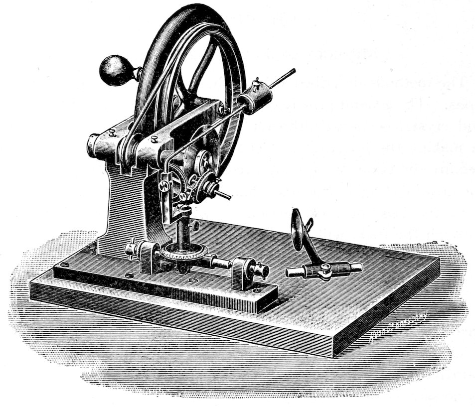
| CHAPTER V. |
| Methods of Preparing Sections. |
| Cutting and Grinding Machines.—Saws.—Cutting.—Grinding. Plates or Laps.—Cementing.—Grinding.—Mounting.—Cleaning and Finishing.—Convenient Apparatus for work. |
117 |
| |
|
| CHAPTER VI. |
| Chemical and Mechanical Tests. |
| Chemical Tests on Crystal in Section: Carbonates, Gelatinizing Silica.—Etched Figures.—Heating Section to Redness.—Methods of Isolating Crystals or Fragments for Testing: Specific Gravity Separation, Electro-magnetic Separation, Chemical Separation.—Micro-Chemical Reactions: Borichy’s Method, Behren’s Method, Special Tests. |
129 |
| |
|
| APPENDIX. |
| Brief Scheme of Classification into Systems by Optical Determinations.—Tables of Double Refraction (maximum) and Indices of Refraction (mean).—Diagram, showing relation between strength of double refraction, interference colors and thickness of section.—Order of Consolidation of the Constituent Minerals in Plutonic Rocks.—Optical Scheme with Special Introduction. |
141 |
| |
|
| Index. |
149 |
ix
CONVENTIONS AND ABBREVIATIONS.
a = The assumed direction of the ether vibrations of the fastest
ray.
b = The assumed direction of the ether vibrations of the ray
with intermediate velocity.
c = The assumed direction of the ether vibrations of the slowest
ray.
In some American Text-Books (by Iddings, Winchell & Phillips)
a = X, b = Y and c = Z.
a′ = The assumed direction of the ether vibrations of the faster
ray in the given section.[1]
c′ = The assumed direction of the ether vibrations of the slower
ray in the given section.
(+) = Optical character positive.
(−) = Optical character negative.
|| = Parallel to.
(γ − α) = The difference between the indices of refraction of
the slowest and fastest rays, respectively, transmitted by the crystal,
and indicates in decimals the relative strength of the double
refraction.
n′ = The mean index of refraction;[2] hence
= α + β + γ
3 or ε + 2ω
3.
α = Index of refraction of the fastest ray.
γ = Index of refraction of the slowest ray.
a, b and ć relate to the crystallographic axes commonly represented
by these letters.
2E = the apparent axial angle measured in air, 2V being the
true angle.
Bxa· = The acute bisectrix.
Bxc· = The obtuse bisectrix.
Ax. pl. = The axial plane, i. e., the plane containing the two
“optic axes.”
xElongation relates to the appreciable extension often shown by
the crystal section. A crystal of long prismatic habit, cut about
parallel to the ć axis, would show marked elongation; while a tabular
crystal (like mica) would show elongation if cut at right
angles to the tabular faces. At times, of course, no elongation is
appreciable, as in the case of granular or broken crystals or where
the cross-section is essentially square or octagonal. Very often
the relation of the cleavage is given to the elongation and also to
the directions a′ and c′, which makes it possible to test for a′ and c′
even when no marked elongation can be observed.
Minerals in Rock Sections.
1
CHAPTER I.
Introductory Optics for Optical Mineralogy.
The object of this introduction is merely to give a practical discussion
of elementary optics, as applied to optical mineralogy,[3]
and no elaborate discussion of this important subject will be attempted.
The explanations will be made as simple as possible,
and, in most cases, only the optical phenomena will be described
without entering into a theoretical discussion as to the cause of
these phenomena.
Light[4] may be regarded as transmitted in straight lines by vibrations
of the “ether,” taking place at right angles to the direction of
transmission.
Ordinary light is light with the ether vibrations in all possible
directions, the path described by any particle of ether constantly
changing.
Plane polarized light is simply light with the ether vibrations all
parallel to one plane passing through the direction of transmission.
By experiment it has been proved that there exists a very close
relation between the optical properties of crystals and their other
physical properties, such as form, color, transmission of heat, etc.
Therefore it is often possible, by a careful optical investigation of
2a crystal section, to determine important crystallographic facts,
even in the absence of any distinct outline.
The Effects Produced by Crystals on Transmitted Light.
Consider that a series of optical tests are made on all possible
sections[5] of crystals in the six systems, and the manner in which
these crystals affect transmitted light ascertained.
Isotropic Crystals: It will be found that all sections of Isometric
crystals transmit light with equal velocity in all directions; that is,
the crystals are optically equivalent in all directions and, hence, can
produce no double refraction.[6] In these crystals any section, however
cut, will transmit all the rays of light, incident to the surface at
right angles, with no change.[7] The same is true of Amorphous
bodies, glass, etc., unless they have been subjected to strains or peculiar
conditions during cooling. A single image is seen through
these isotropic sections.
Anisotropic Crystals: It will also be found that nearly all sections
(the exceptions being given later) of crystals in the remaining
five systems, produce quite a different effect on transmitted light.
In these crystals the velocity of transmission of light varies with
the vibration direction of the light rays. This property, called
double refraction,[8] seems to result from the power of resolving a
ray of ordinary light, with ether vibrations
in all directions, into two rays with
ether vibrations in planes at right angles
to each other; the two resulting rays traversing,
usually, divergent paths in passing
through the section.
The mineral calcite (Iceland spar)
exhibits this property to a marked degree,
and in certain sections will show a double image, Fig. 1.
That the vibration directions of the two doubly refracted rays are
3in planes at right angles to each other, can be easily proved by using
a nicol prism.[9] In most cases the separation of the two images is so
slight as not to be perceived by the eye, and the practical method
of testing a crystal section for double refraction will be given
later, p. 27.
The crystals that show double refraction are further divided into
two groups, uniaxial and biaxial:
(1) Uniaxial, or those in which the optical characters are symmetrical
to one direction, called an optic axis. This optic axis is
the crystallographic vertical axis, ć; and parallel to this direction
there is a single value only for the light velocity and no double
refraction takes place.[10] Hence any section parallel to the base
(001) being at right angles to the optic axis, acts like a section
of an isotropic crystal and transmits all the perpendicularly incident
rays of light with no change. In any other section double
refraction takes place and it can be proved by using a nicol prism
that the two rays have ether vibrations, one in the plane passing
through the incident ray and the ć axis of the crystal, and the
other in a plane at right angles thereto, hence in the basal plane.
This latter ray, which has a constant velocity, is called the ordinary
ray O; and the other ray, with velocity varying with the
inclination of the section to ć, is called the extraordinary ray
E.[11]
The vibration directions are either parallel or symmetrical to
cleavage cracks and crystal outlines. In sections parallel to the
optic axis, the two doubly refracted rays have the maximum difference
in velocity of transmission, and hence their vibration directions
are called principal vibration directions[12] and the plane containing
them an optical principal section. In these sections the
refractive index of the ray vibrating parallel to ć (extraordinary
4ray) is denoted by ε, and that of the ray vibrating parallel to the
basal plane (ordinary ray) by ω.[13]
To this group belong all Tetragonal and Hexagonal crystals.
(2) Biaxial, or those in which the optical characters are no
longer symmetrical to an optic axis but to three planes at right
angles to each other (for monochromatic light). These crystals
have, however (for light of each wave-length and for each temperature),
two directions parallel to which there is a single value only
for the light velocity and hence no double refraction. These directions
are called “optic axes.”[14] An investigation of these biaxial
crystals shows that of all the rays traversing these crystals there
are three rays which advance with maximum, minimum and some
intermediate velocity. The vibration directions of these three rays
are called the principal vibration directions and are at right angles
to each other (being the intersections of the three planes above
referred to). The direction of ether vibration of the fastest ray is
denoted by a, of the slowest ray by c, and of the ray advancing
with intermediate velocity by b.[15] Each of the three planes, containing
two principal vibration directions, is called an optical principal
section. The index of refraction of the a ray is denoted by α,
of the b ray by β, and of the c ray by γ.
To this group belong all crystals in the Orthorhombic, Monoclinic
and Triclinic systems.
In the Orthorhombic system, the principal vibration directions
are parallel to the crystallographic axes; hence all pinacoidal sections
contain two of these principal vibration directions. In all
sections parallel to the three crystallographic axes ă, ƃ and ć, the
vibration directions are parallel or symmetrical to cleavage cracks,
crystal edges, etc.
5In the Monoclinic system, one principal vibration direction is
parallel to the ortho axis ƃ, the other principal vibration directions
are in the plane of symmetry, at right angles to ƃ, but are
not parallel with either the vertical axis ć or the clino axis á. In
clino pinacoid (010) sections the principal vibration directions
will make definite angles with crystallographic lines, such as
cleavages or crystal outlines. These angles are called extinction
angles. They will vary, in this system, with reference to the
direction of the ć axis from a maximum on the clino pinacoid (010)
to 0° on the ortho pinacoid (100), when the vibration directions of
the two doubly refracted rays will be parallel and at right angles to
the plane of symmetry. Hence the vibration directions are parallel
or symmetrical to cleavages, edges, etc., only in sections parallel to
the ortho axis ƃ; but in all other sections are unsymmetrical.
In the Triclinic system, the principal vibration directions are not
parallel to the crystallographic axes, and there is no definite relation
between these directions and the crystallographic axes; hence in
all possible sections there will be extinction angles.
In all biaxial crystals the two optic axes are inclined to each
other, making what is called the axial angle, 2V, the apparent
angle measured in air being 2E. The optic axes lie in the plane,
called the axial plane, which contains the principal vibration directions
a and c. The axial angles are bisected by these principal
vibration directions, the direction bisecting the acute angle being
called the acute bisectrix, Bxa, and that bisecting the obtuse angle
the obtuse bisectrix, Bxo. An approximate idea of the value of the
axial angle can be obtained by the use of the petrographical microscope,
as described later, p. 47. The axial angle is often a convenient
distinction between such minerals as muscovite and biotite.
The axial angle will vary with the temperature and with light of
different wave-length or color, and this variation is called dispersion
of the optic axes. Dispersion of the principal vibration directions
also takes place in monoclinic and triclinic crystals, but can be
usually disregarded.
In closing it is very important to remember that any section of
an anisotropic crystal (not at right angles to an optic axis) will
always transmit two rays of light with different velocities and with
vibration directions in planes at right angles to each other. Isometric
crystals, of course, produce no double refraction of light.
7
CHAPTER II.
The Petrographical Microscope.[16]
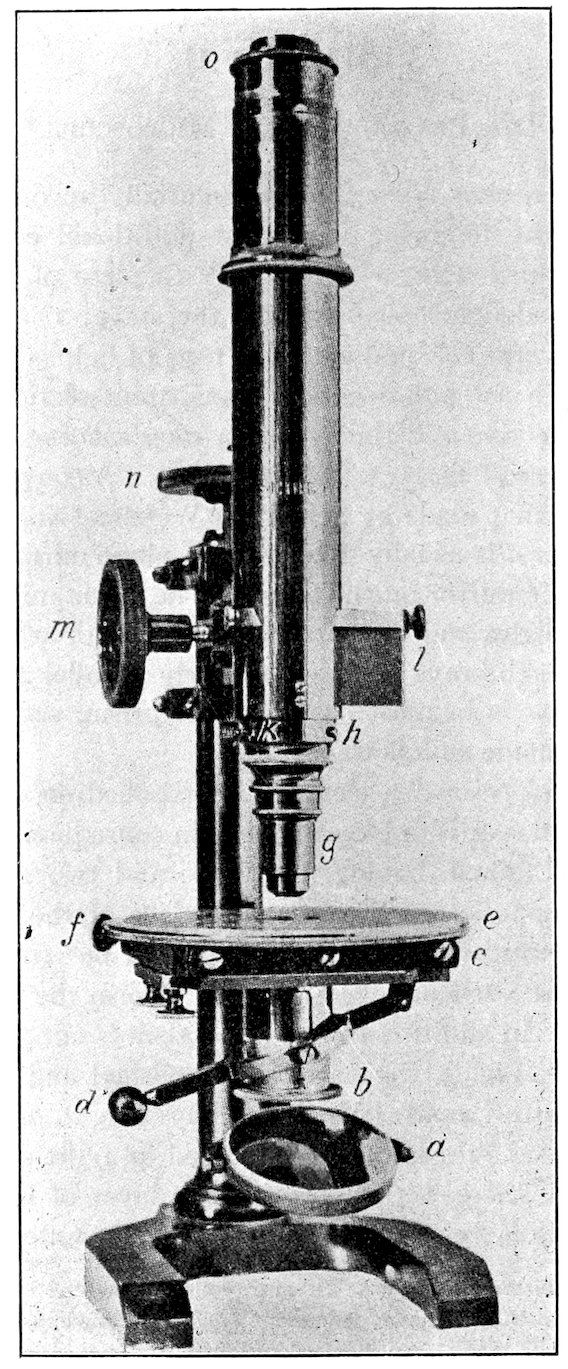
The petrographical microscope is essentially an ordinary microscope[17]
with the following important additional equipment. It
must be provided with: 1° a polarizer (a piece of apparatus for
giving polarized light) placed below the stage; 2° an analyzer (a
piece of apparatus for analyzing the rays of light after they have
passed through the polarizer and transparent section) placed between
the objective and the eye; 3° a stage rotating about an axis
which is the line of sight of the microscope. A convenient type of
microscope is that made by Seibert of Wetzlar (No. 11 a), Fig. 2.
The reflector a is usually fitted with a plane mirror on one side,
and a parabolic mirror on the other. The plane mirror should be
used with sunlight, and the parabolic mirror with artificial light, in
order to make the rays of light as nearly parallel as possible.
The polarizer is in most cases a nicol prism, set in a suitable
frame b, and made as follows:
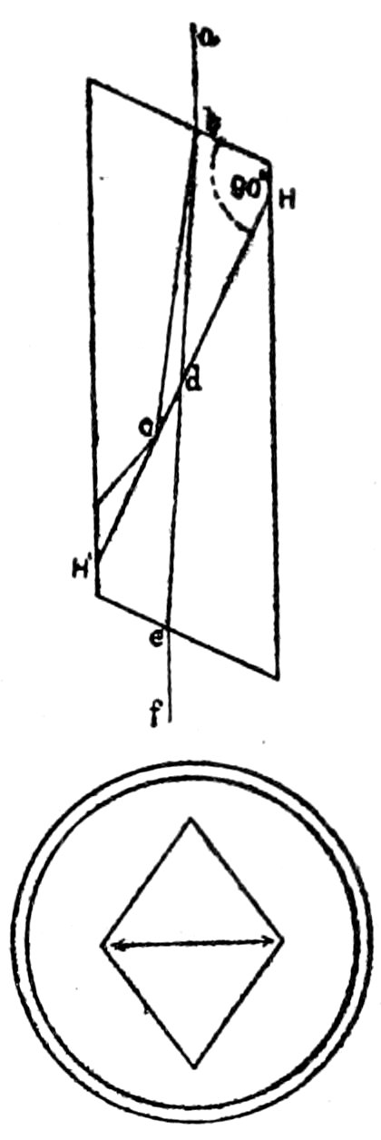
For the nicol prism “a cleavage rhombohedron of calcite (the
variety Iceland spar is universally used in consequence of its transparency)
is obtained, having four large and two small rhombohedral
faces opposite each other. In place of the latter planes,
two new surfaces are cut, making angles of 68° (instead of 71°)
with the obtuse vertical edges; these then form the terminal faces
of the prism. In addition to this, the prism is cut through in the
direction HH′, Fig. 3, the parts then polished and cemented together
again with Canada balsam. A ray of light, ab, entering the
prism, is divided into two rays polarized at right angles to each
other. One of these, bc, on meeting the layer of balsam (whose
refractive index is less than that of the ray bc), suffers total reflection,
8and is deflected against the blackened sides of the prism and
extinguished. The other, bd, passes through and emerges at e, a
completely polarized ray of light, that is, a ray with vibrations in
one direction only, and that the direction of the
shorter diagonal of the prism.”[18] The vertical
plane through the shorter diagonal may be called
the plane of vibration[19] of the nicol.
9
The polarizer must be below the stage c, and
is generally adjusted so as to have its plane
of vibration parallel to the N. and S. cross-wire
in the eye-piece o. It is important to
know the direction of the plane of vibration
of the polarizer or lower nicol, as we can
then determine, when absorption of light occurs
in a mineral, the direction in this mineral
parallel to which the absorbed rays are vibrating.
The polarizer slides in an outer shell
or frame, and, by means of a lever d, can easily
be raised or lowered.
A convenient test for the location of this
plane of vibration of the polarizer is as follows:
Make use of a section of biotite, cut at
right angles to the basal plane, hence showing the basal cleavage
cracks. Biotite has the property of absorbing to a marked extent
the light vibrating parallel to these cleavage cracks. Rotate such a
section on the stage of the microscope until the position of maximum
darkness is reached and when such is the case the plane of vibration
of the polarizer must be parallel to these cleavage cracks.
On the top of the nicol is placed the condensing lens for getting
convergent light, and the adjustments are so arranged that when
the nicol is up as far as it will go, the condensing lens[20] is brought
almost in contact with the lower surface of the transparent section
resting on the stage.
10The rotating circular stage e is supported on a suitable frame c,
and arranged so that its axis of rotation coincides with the line of
sight of the microscope. The stage is graduated, and, by means
of an index fixed to the frame, the angular rotation can always be
obtained. It is also provided with two adjusting screws[21] f, by
means of which the axis of rotation can be accurately centered.
The method of centering is as follows: Bring some prominent
mark in the section exactly in coincidence with the intersection of
the cross-wires in the eye-piece. Rotate the stage 180°, and correct
one half the error by means of the centering screws, and the
other half by moving the section on the stage. Check the result
by rotating the stage 180° again, and if necessary repeat the corrections
in the same way until the adjustment is satisfactory.
The objective[22] g screws into the collar h, which has a slot k, in
the upper portion, for the introduction of a sensitive color plate,
a one quarter undulation mica plate or a quartz wedge.[23]
The slot k is so arranged that, when the sensitive color plates
are introduced, the vibration directions of these plates will make
an angle of 45° with the planes of vibration of the crossed nicols,
and the interference color will thus be at its maximum intensity.
A revolving nose-piece is sometimes used which can be attached
to the collar h and arranged to carry two or three objectives, which
can thus be very quickly brought into position for use. This is
convenient in passing rapidly from observations with parallel light
to observations with convergent light, which must be made with a
high power objective. The difficulty is that recentering is generally
required. The modern microscopes are provided with a clip for
holding the objectives, instead of the screw-thread collar h.
The analyzer[24] or upper nicol is contained in the frame l, which
11is arranged so as to slide in and out of the tube of the microscope.
The plane of vibration of the analyzer is fixed by the instrument
maker so as to be at right angles to the plane of vibration of the
polarizer, hence in the Seibert microscope parallel to the E. and
W. cross-wire in the eye-piece. Consequently when the frame l
is pushed into the tube, the analyzer is introduced in the line of
sight between the objective and the observer’s eye, with its plane of
vibration at right angles to the plane of vibration of the polarizer;
that is the nicols are crossed. When the nicols are crossed, if they
are properly adjusted, no light can pass through to the eye and
the field of view should be dark.[25]
The eye-piece[26] o fits into the top of the tube, and, by means of
a little projecting piece fitting into a slot in the frame, can always
be adjusted so as to have its cross-wires parallel to the planes of
vibration of the two nicols.[25]
Some instruments are provided with an additional slot in the
tube between the analyzer and the eye-piece for the introduction
of a Bertrand lens, which is used to magnify the interference figures
produced by convergent light.
The first approximate focusing is made by the screw m, and the
fine adjustment by the screw n.
In focusing always start with the objective very near the section,
and move it away until the right focus is obtained. Never move
down towards the section in obtaining the focus, as there is danger
then of striking the objective against the section.
For cleaning the microscope xylol can be used, as it will not
injure the lacquer. To lubricate any of the parts use a small
quantity of soft tallow, good clock oil or paraffin oil.
13
CHAPTER III.
Investigation of Microscopic and Optical Characters of Minerals.
Characters of Opaque Minerals, observed by reflected light.
The minerals which remain perfectly opaque in thin rock sections
have usually metallic lustre and are very minute in size, as is the
case with the iron ores.
When the metallic minerals of a rock specimen are distinctly
seen with the unaided eye, it is rarely necessary to make a section
for their determination, as this can more easily be done by any of
the well known blowpipe methods.
Form, Lustre, Color, Cleavage, etc., are recognized in the same
way as in the case of macroscopic specimens. In order to make the
observations by reflected light alone, the beam of light from the
reflector-mirror must be cut off by holding the hand over the mirror
or by moving the mirror.
Characters of Transparent Minerals, observed by transmitted
light. The petrographical microscope for these observations is
supposed to be in the condition of an ordinary microscope, both
nicols being out of the field and a strong beam of light coming up
through the transparent section from the reflector below.
The characters are considered in the order in which they would
most naturally appear to the observer during a complete investigation
with the microscope.[27]
14
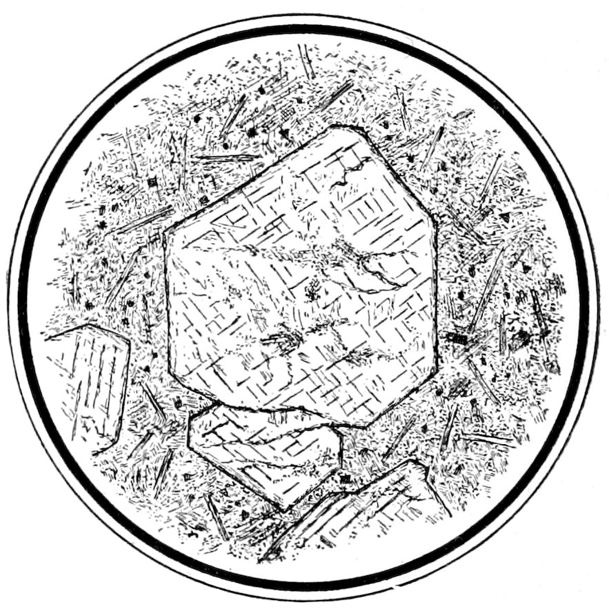
Fig. 4.—Idiomorphic augite crystals in camptonite. The section is about at right angles to the vertical axis ć, and shows the intersecting cleavages parallel to the prism of 87° 06′. Keene Valley, N. Y.
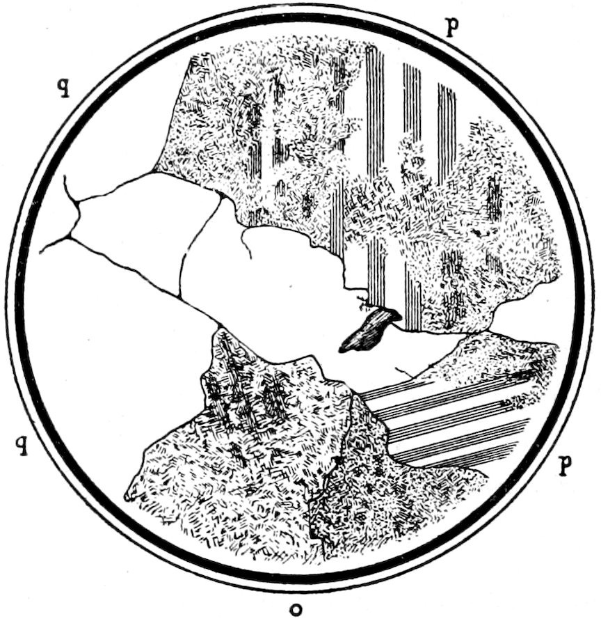
Fig. 5.—Allotriomorphic quartz q, showing no “relief,” plagioclase p and decomposed feldspar o in granite. As seen with crossed nicols.
(a) Form.[28] Crystals bounded by planes, i. e., crystals that have formed when conditions were favorable for complete development. Such crystals are often called idiomorphic or automorphic, see Fig. 4. Crystals that are large in comparison with other accompanying crystals may be called Phenocrysts. Of course crystals, which are not wholly contained within the rock section, will only show the outline of the bounding planes cut by this particular section. In some cases, by a careful study of the outline of several sections of the same mineral and by a measurement of the angles, it is possible to determine the common “crystallographic
15forms” of the mineral. Very misleading outlines may,
however, be observed; as for example the triangular outline of a
section of a cube, with the corner truncated. For measuring the
angles have the stage accurately centered, then bring the vertex
of the angle to be measured to the intersection of the cross-wires
in the eye-piece. Bring one of the sides in coincidence with one
of the cross-wires. Note the reading of the graduated circle and
rotate the section until the other side is in coincidence with the
same wire. Take the reading again and the difference will be the
angle required.
Crystals without bounding planes, whose surfaces are more or
less determined by those of adjacent crystals. Such crystals are
frequently called allotriomorphic or xenomorphic,[29] see Fig. 5.
This allotriomorphic form must not be confounded with the worn
or rounded boundaries of the component grains in clastic rocks.
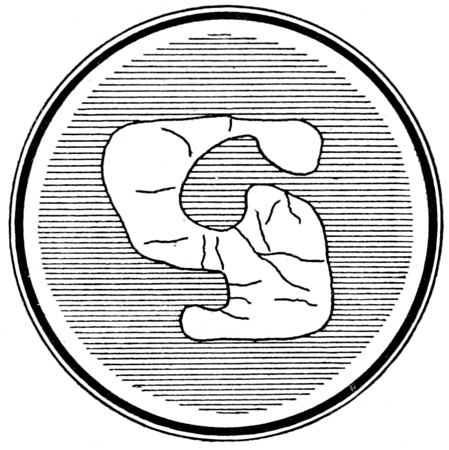
Fig. 6.—Corroded sanidine crystal in perlite.
Corroded Crystals,[30] whose fretted outline is undoubtedly due to
corrosive action of the magma, see Fig. 6.
Broken or Strained Crystals. In some cases what were formerly
larger individuals have been broken or shattered by dynamic action
into much smaller fragments, see Fig. 7, showing crushed rim of
16fragments surrounding feldspar “auge.” In other cases an actual
bending or distortion of the crystal has taken place, and again
sometimes the effect of mechanical stress is only shown by the
so-called “wavy” extinction. See p. 31 and Fig. 7, showing a
carlsbad twin of feldspar that has been bent and therefore shows
marked “wavy” extinction.
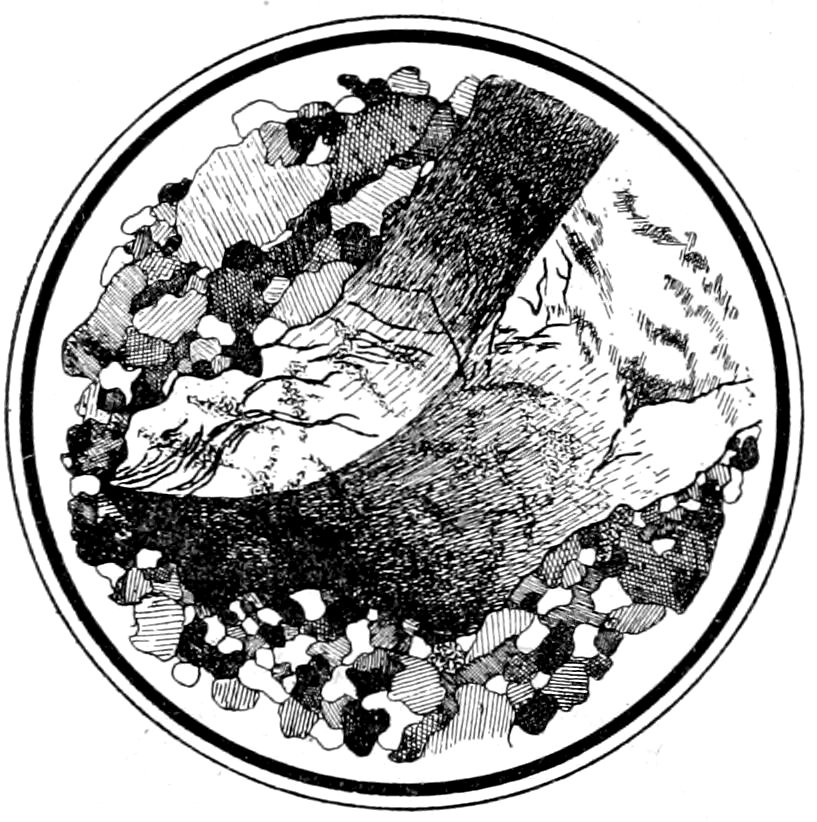
Fig. 7.—Orthoclase “auge” (Carlsbad twin), showing bending and “wavy” extinction, surrounded by crushed rim of mineral fragments. As seen with crossed nicols. “Augen-gneiss,” Bedford, N. Y.—B. 13.
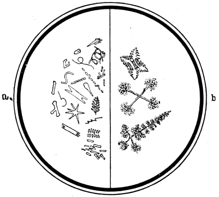
Fig. 8.—Crystallites and Microlites a. Skeleton Forms b.
Crystallites, in general those incipient forms of crystals which
have not yet reached a stage of development sufficient to show
double refraction, see Fig. 8, a. Quite a number of names are used
to describe the different forms that occur.
17Microlites, more or less completely defined microscopic crystals,
which usually show double refraction, but cannot be always specifically
determined, see Fig. 8, a.
Skeleton Forms, resulting from rapid cooling of the magma
occur in some lavas, see Fig. 8, b.
(b) Color. It must be remembered that the colors observed
are always due to transmitted light and may be called “absorption
tints.” Minerals which in hand specimens are opaque are often
colored in sections; and minerals which are commonly colored
may appear colorless in sections. At times color may be given to
a section simply by the presence of a great number of minute
inclusions.
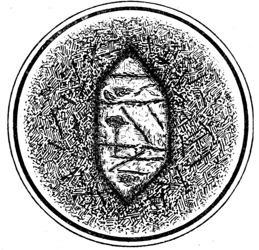
Fig. 9.—Olivine crystal in basalt showing “high relief” and cleavage.
(c) Index of Refraction. n = sin i/sin r. This can be approximately
determined by the appearance of the surface and outline
of a mineral, that is by its relief. The descriptive terms are
of course relative, but in common practice minerals are said to
have medium refraction when the refractive index is between that
of balsam (1.54) and that of calcite (1.60), strong refraction when
higher than 1.60 and weak refraction when lower than 1.54. In
the case of uniaxial and biaxial minerals the mean value of the
indices of refraction is used.
A mineral which has strong refraction appears to have high
relief, i. e., distinct dark contours and a rough or “shagreened”
18surface,[31] which has bright illumination and appears to stand out
above the surfaces of the surrounding minerals with weaker refraction,
see Fig. 9.
A mineral with medium refraction does not show any relief,
hence has a smooth surface and no dark contours, see Fig. 5.
A mineral with weak refraction may also appear to have a
rough surface, but not so marked as in the case of a mineral with
very strong refraction, due to the smaller contrast in indices
between the mineral and balsam.
The practical way of testing for the approximate index of refraction
or the relief of a mineral is to make use of the lens for convergent
light, which is placed on top of the lower nicol immediately
below the section.
By lowering[32] the lens the character of the relief of a mineral
section is made very apparent.
In order to become familiar with the way in which the “relief”
or appearance of the surface indicates the strength of the refractive
index, the student may use a long glass slide on which are embedded
in balsam (1.54) small fragments of different minerals, for
example: Sodalite (1.483), orthoclase (1.523), quartz (1.547),
topaz (1.620), hornblende (1.631), augite (1.70), epidote (1.751),
zircon (1.95) and rutile (2.712).
Determinations of refractive indices in sections by the methods
19of Chaulnes,[33] Sorby,[34] or total reflection are accompanied by many
difficulties and may fail to give satisfactory results. The
Becke method, however, often furnishes a convenient means of
determining the relative values of the refractive indices of adjoining
minerals or of minerals embedded in balsam. This is of
especial service when one of the minerals is known and hence its
refractive index.
Becke Method.[35]
Suppose two adjoining minerals, in a thin rock section, to be
singly refracting and to have their plane of contact vertical, i. e.,
parallel to the optic axis of the microscope.
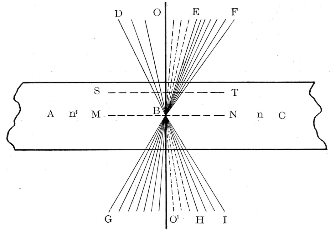
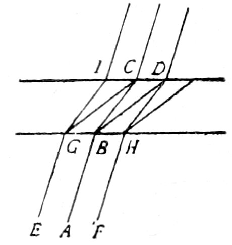
Let A and C, Fig. 10, be two such sections with the plane of contact
OO′ vertical, A having a lower refractive index than C, and
consider only the direction of the rays within the section, neglecting
the refractive effect of the air, glass and balsam.
A beam of transmitted light contains besides normal rays convergent
rays, which pass through the section as indicated in Fig.
10. Consider now the cone of light rays GBI. The rays O′G on
meeting the plane of contact OO′ will be somewhat concentrated
and deflected by the higher refractive index of C and will continue
as the cone EF. Some rays as O′H will, on meeting the contact
plane, be totally reflected and will continue as the cone OE, while
the rest of the rays HI will be dispersed and deflected by the weaker
refractive index of A, continuing as the cone OD. Hence, more
light rays will emerge on the side of the contact plane where
the substance of higher refractive index lies, and there will
be a concentration of illumination on this side producing the
so-called “bright line.”
20
In practically making the test with a petrographical
microscope remove the polarizer, analyzer and condensing lens,[36] and
introduce below the section a small light-stop, to reduce in size the cone of incident light.[37] The
adapter, holding this light-stop, should be adjustable so that the stop
can be lowered sufficiently to produce the best results. The smaller the
contrast between the indices of refraction the smaller the incident cone
of light should be, as best results are obtained when this cone is little
larger than twice O′H, Fig. 10, all the O′H rays being
then totally reflected. The more of the HI rays that pass through,
the brighter will be the OD cone and the less sharp the contrast
in illumination. A high power objective[38] should
be used, as those with small aperture and great focal length do not give
good results. Focus on the dividing plane and adjust until equal illumination
is observed on both sides and the trace of the plane resembles a fine thread,
the focal plane being at MN. Then raise the objective
slightly, thus moving the focal plane to ST, when a bright
line or band will appear on the side of the stronger refracting
substance, the width of the line depending on the contrast between
n and n′, becoming narrower as n and n′
approach each other in value. On raising the objective still further the line
21broadens and finally disappears. If the objective is lowered instead
of raised the reverse phenomenon will take place, the bright
line appearing on the side of the weaker refracting substance.[39]
When the indices are nearly the same a bright line will appear on
both sides and it is important then to make the cone of incident
light as small as possible and to select the brighter line.
With doubly refracting minerals, each set of doubly refracted
rays would suffer total reflection under somewhat different conditions
and there would be no one point B (as in isotropic minerals)
where no bright lines would appear. However, if the cone of incident
light is small enough in diameter, the test will be practically
obtained as described. The Becke test can often be made with a
medium power objective[40] without removing the polarizer and condensing
lens, provided the condensing lens be lowered sufficiently.
It may also prove convenient to turn the reflector a little sideways.
The thinner the section the more distinct will be the phenomenon.
The contact plane must be clear and not coated with opaque
decomposition products.
When the plane of contact OO′ deviates considerably from
parallelism with the optic axis of the microscope a disturbance of
the phenomenon may be expected and no satisfactory results be
obtained. In general under these conditions the “bright line,”
both on raising and lowering the objective, will remain on the side
of the overlapping substance, without regard to the relative values
of the indices.
The refractive index of the cementing material should not be
very much lower than that of either of the thin sections, as the
result would then be to disperse the emerging rays too much and
dim the effect. In the case of distinguishing between minerals of
high refractive power, such as augite and garnet, methyliodide is
recommended instead of balsam.
In the case of doubly refracting crystals, the lower nicol (polarizer)
must be retained, if it is desired to obtain the relative refractive
index of one of the two rays, either with respect to the balsam
or to a ray in an adjoining crystal with a parallel vibration direction.
For determining vibration directions of rays and the faster
and slower rays in two adjoining sections see later, pp. 31 and 33.
22The method of Schrœder van der Kolk[41] can also be employed for
the same purpose as the Becke test. The ordinary objective (Seibert
No. II) is used, and the method essentially consists of darkening
a portion of the field by means of the finger or a plate
inserted below the polarizer. The condenser lens must be lowered
beyond the sharp focus of the edge of the shadow (on raising
the condenser the following phenomena are reversed). As the
shadow approaches the contact between two minerals a bright line
will appear on the edge of the “far” mineral, if its refractive
index is the higher, and a dark line on this same edge if its index
is lower than that of the “near” mineral. The indices of the two
rays in doubly refracting minerals must be determined by the aid
of the polarizer.
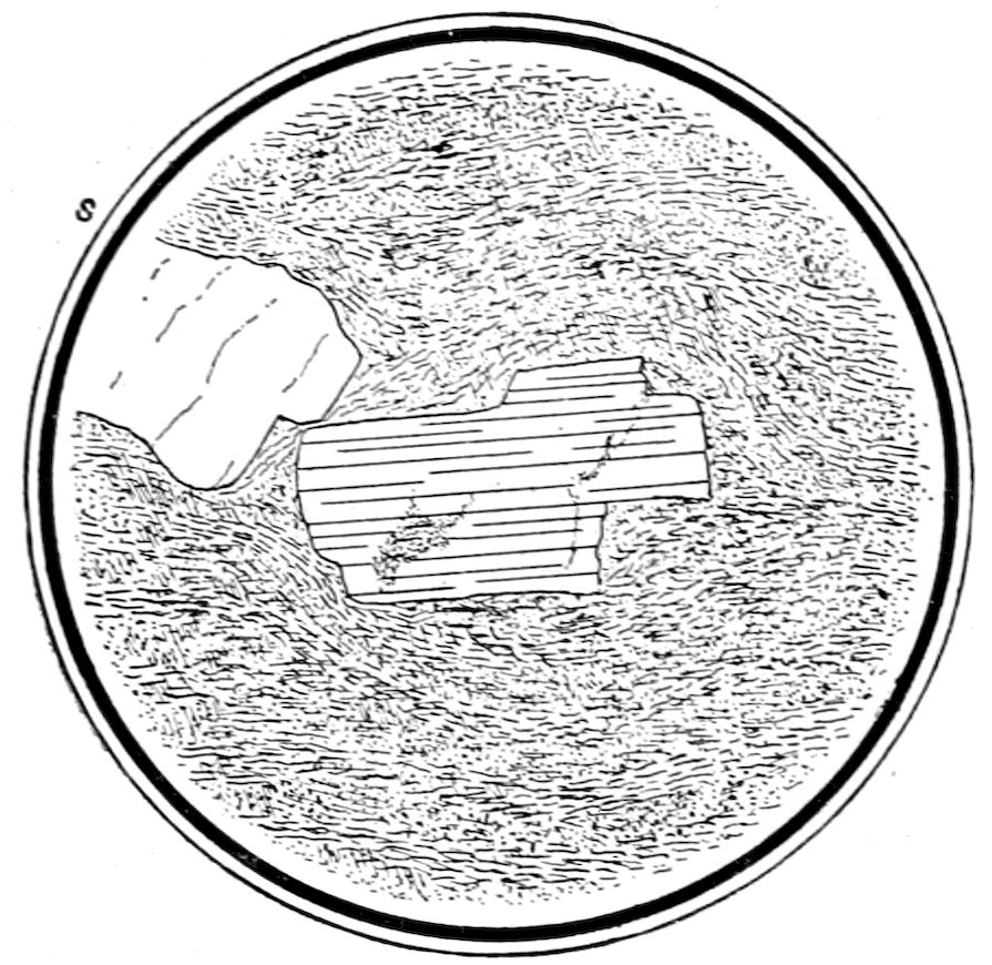
Fig. 11.—Biotite, showing perfect cleavage, in rhyolite.
23(d) Cleavage,[42] which appears as more or less distinct and regular
lines or cracks, see Figs. 11 and 12. These cleavage cracks
may be parallel or intersect, depending on the position of the section
relative to the cleavage planes of the crystal.
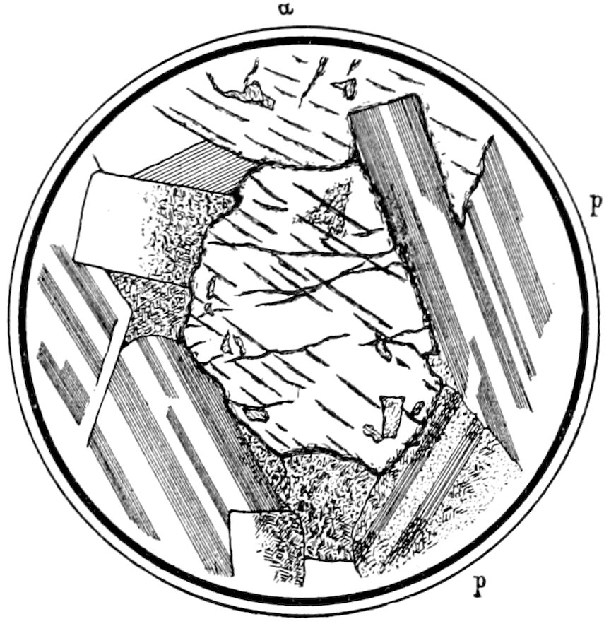
Fig. 12.—Augite a, showing good cleavage, and plagioclase p in diabase. The plagioclase shows “polysynthetic” twinning between crossed nicols.
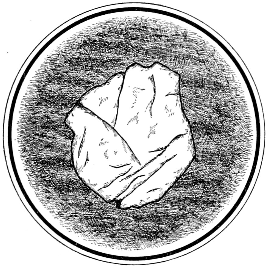
Fig. 13.—Garnet in mica schist, showing fracture. Franconia, N. Y.
Cleavage is sometimes best observed by slightly lowering the
condensing lens under the section.
When sections show intersecting cleavage cracks it is often possible
24to recognize the mineral by its known cleavage angle, as in
the case of amphibole and pyroxene.
(e) Fracture, which appears as irregular and non-parallel cracks,
see Fig. 13.
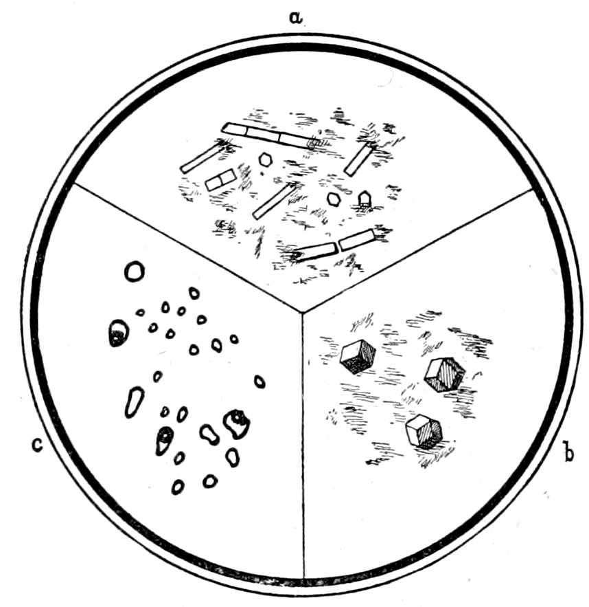
Fig. 14.—Apatite in feldspar a. Garnets in quartz, Branchville, Ct., b. Liquid inclusions of CO2, some showing gas bubbles, in quartz c.
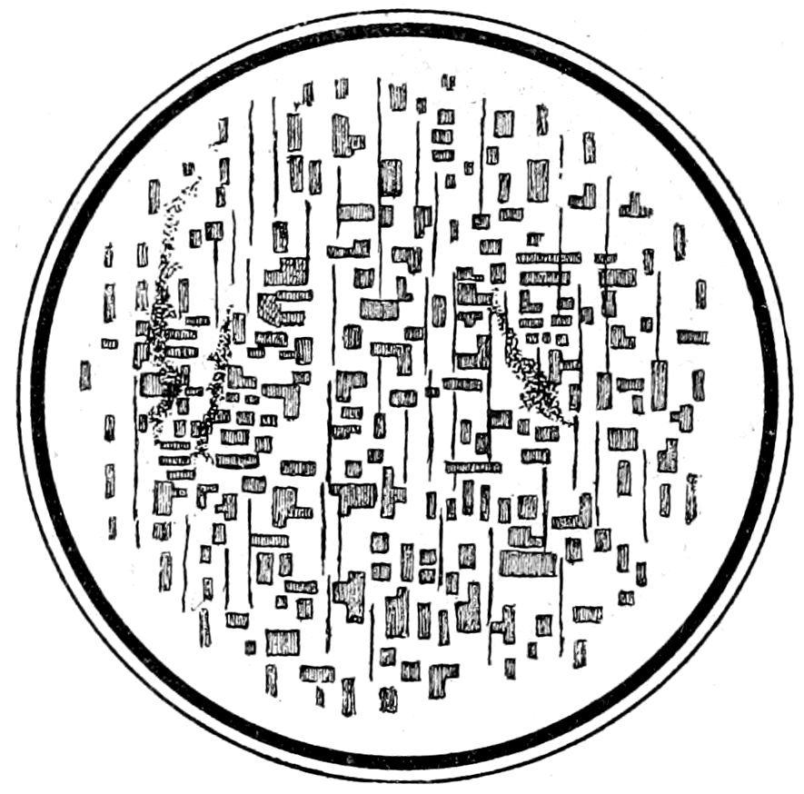
Fig. 15.—Enstatite showing “Schiller” Structure.
(f) Inclusions, which may be solid (either distinct crystals or
glass), fluid or gas, see Fig. 14. These inclusions are distinguished
by the fact that the solid inclusions generally have sharp contours,
the fluid inclusions distinct dark borders, and the gas inclusions
broad dark borders more distinctly marked than those of the fluid
inclusions. The fluid inclusions often contain a bubble of gas.
25The inclusions may have a definite or indefinite position in the
crystal in which they occur, and can sometimes be more distinctly
seen by using convergent light or a “spot” lens.
(g) Schiller Structure. “Is that in which cavities of definite
form and orientation (‘negative crystals’) are developed along certain
planes and filled or partially filled by material dissolved out
of the enclosing crystal,”[43] see Fig. 15.
Characters Observed by Polarized Light.
The polarized light is obtained by passing the beam of light
from the reflector through the polarizer or lower nicol,[44] which
must be in place below the stage of the microscope. White light
is supposed to be used.
Pleochroism, that property which all anisotropic minerals have,
to a greater or less extent, of absorbing certain colored rays in
certain directions, thereby showing different colors in different
directions by transmitted light. Uniaxial minerals are dichroic
showing two differences in color, produced by the rays which
vibrate parallel to the direction of the vertical axis ć and the plane
of the basal axes. Biaxial crystals are trichroic showing theoretically
three differences of color produced by rays with vibration
directions corresponding very nearly to those of the three principal
vibration directions.[45] Any given section of a biaxial crystal will,
of course, appear only dichroic.
The practical way of testing for pleochroism is as follows: Revolve
the stage, carrying the section, when a change in the color
of the mineral will be noticed, if it is pleochroic. This pleochroism
26may appear as an actual change in color or simply as a change in
the shade of the same color. At times it may be so weak as
hardly to be noticed, when it is best to make the test with the
condensing lens in position immediately under the section, or by
rotating the lower nicol instead of revolving the stage. The color
of the light, vibrating parallel to certain definite crystallographic
directions in minerals, is often very characteristic.
In some cases there may be such strong absorption of one of the
rays, that, when the vibration direction of this ray is over the plane
of vibration of the polarizer, practically no light is transmitted and
the section appears dark. Strong absorption is characteristic of
certain minerals, such as biotite, amphibole, tourmaline and allanite
and takes place parallel to definite directions in these minerals.
Pleochroism may often be noticed with ordinary light in the
case of hand specimens.
Characters Observed with both Polarizer and Analyzer[46] in Position, that is with “Crossed Nicols.”
When the nicols are accurately crossed, the field should be
quite dark, and if this is not the case the adjustments must be
looked to. The condensing lens should be removed for these
tests as they are to be made with parallel light, but as a matter of
convenience instead of removing the condensing lens, the polarizer
with the lens on top may be lowered, when the results will be about
the same as with parallel light. White light is supposed to be used.
Isotropic Character. Sections of isotropic crystals are perfectly
dark and remain so during a complete rotation of the stage
through 360°. The explanation is very simple. Light being
transmitted by an isotropic crystal in all directions without double
refraction; it follows that the light from the polarizer, after having
passed through the section, comes to the analyzer still vibrating
in the plane of vibration of the polarizer. Hence it is entirely cut
out by the analyzer.
Amorphous transparent substances act in the same way and remain
dark during complete rotation of the stage.
27Optical anomalies, i. e., double refraction, may occur in isometric
crystals and in amorphous substances that have been subjected to
strains.
Anisotropic Character. Sections of anisotropic crystals, having
the property of double refraction, produce in general some
interference or polarization color, except as mentioned later. The
popular explanation is as follows:
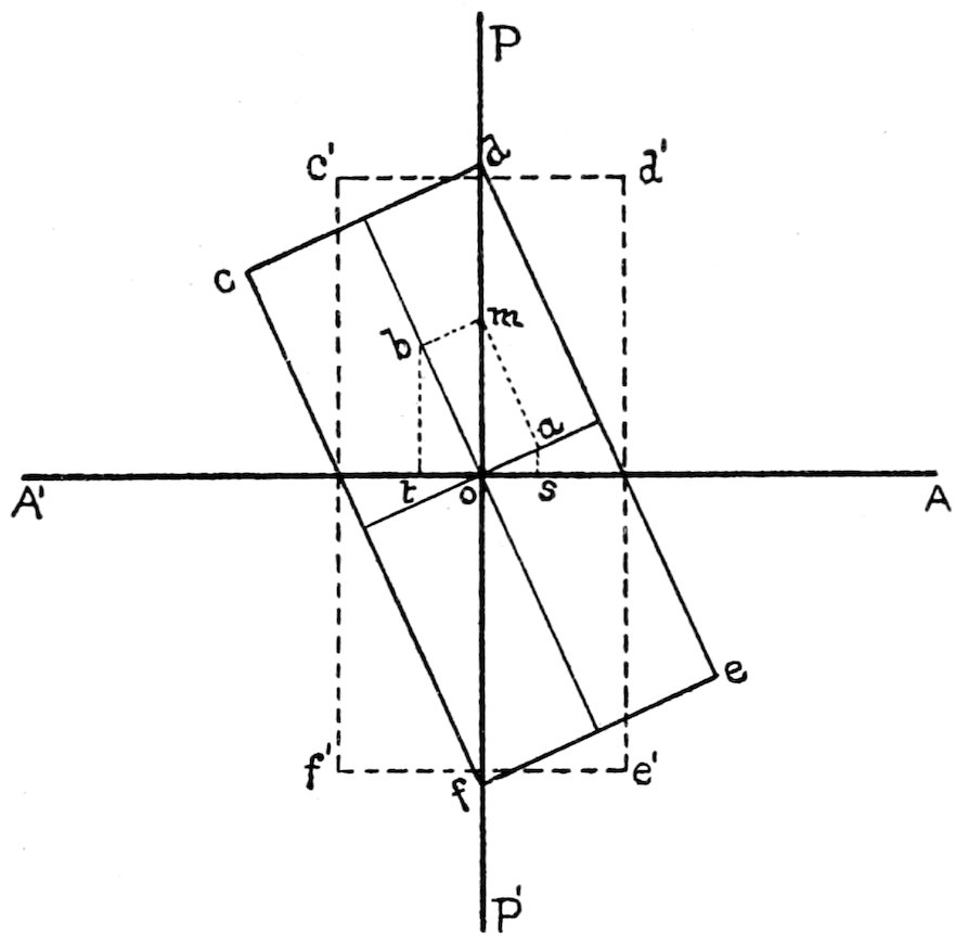
In Fig. 16, let PP′ be the plane of vibration of the polarizer,
and A′A the plane of vibration of the analyzer. All the light,
after it has passed through the polarizer, is vibrating parallel to
PP′ when it reaches the lower side of the transparent crystal, cdef,
on the stage of the microscope. In this transparent section let
ob and oa be the two directions of vibration, i. e., the only two
directions parallel to which rays of light can vibrate in passing
through the section.
Let om represent the amplitude of vibration of a ray from the
polarizer. When this ray reaches the section it cannot get through
it vibrating in the direction om, but is doubly refracted and of the
two resulting rays, one gets through vibrating in the direction ob
and the other vibrating in the direction oa. From m draw perpendiculars
28to ob and oa. Then according to the law of the
parallelogram of forces ob will represent the amplitude of vibration
of the ray passing through the crystal vibrating in the direction
ob, and oa will represent the amplitude of vibration of the ray
passing through the crystal vibrating in the direction oa. We
will thus have two rays passing through the crystal, polarized at
right angles to each other.
Consider now the general question of the transmission of the
doubly refracted rays through a plate. Whatever the angle of the
parallel incident rays, each ray as AB, Fig.
17, is resolved, as just described, into two rays
BC and BD, polarized at right angles to each
other and following (usually) different paths
in the plate. On emergence these follow parallel
paths. Among the incident rays there are
rays EG and FH, such that one component
of FH will emerge at D with one of the components
of AB, and one component of AB
and one component of EG will emerge at C.
Hence from every point of the upper surface of the plate there will
emerge two rays and these rays will have travelled through different
paths in the plate with different velocities and will have their
vibrations at right angles to each other.
When these doubly refracted rays come to the analyzer, whose
plane of vibration is A′A, they cannot get through vibrating in their
present directions, but components of these rays, such as ot and os,
can get through vibrating parallel to the plane A′A.
Hence we have two series of rays coming to the eye, polarized
in the same plane, but one set slightly in advance of the other.
These rays will “interfere” and produce some interference or
polarization color.[47] In using white light whenever one of two
light rays of the same color has suffered a “retardation” of just
one wave-length (or even multiple thereof) the color will be extinguished;
and when the “retardation” is one half wave-length
(or even multiple thereof) the color will be intensified. Therefore,
some tints will be extinguished and others intensified, the
29combination resulting in the production of some definite interference
color. Of course in the case of monochromatic light
the thickness of the section may be such that “destructive interference”
takes place producing no color (darkness).
Now suppose the stage to be rotated until the section cdef
takes the position c′d′e′f′. The section will be found to be dark
and no interference color will be seen. This is due to the fact that
the directions of vibration in the section are parallel to the planes
of vibration of the crossed nicols, consequently the light passes
through the section still vibrating parallel to the plane PP′ of the
polarizer and is all cut out by the analyzer. Darkness will occur
every 90° and therefore four times during a complete rotation of
the stage. The interference color is also observed to vary in
intensity, but not in color, and to be at its maximum 45° from the
positions of darkness.
Sections of uniaxial crystals at right angles to the optic axis act
like isotropic substances and remain dark during a complete rotation
of the stage. In the biaxial crystals, a section at right angles
to an “optic axis” shows uniform illumination[48] which does not
change as the stage is rotated.
The only way to find out whether sections that remain dark
are isotropic, or uniaxial at right angles to an optic axis, is to
test them with convergent light as described later, see p. 40.
Interference Colors. The interference color shown by any mineral
section depends on three factors: 1° the strength of the double
refraction (γ − α = the difference between the refractive indices of
the slowest and fastest rays); 2° the position of the section in the
crystal; 3° the thickness of the crystal section.
To eliminate, so far as possible, the variation due to the optical
orientation of the section, care must always be taken to obtain the
maximum interference color given by the different sections of the
same mineral in the rock section. Sections giving the maximum
color are those parallel to the ć axis in uniaxial minerals and those
parallel to the axial plane in biaxial minerals.[49] Hence such sections
in convergent light never show the emergence of an optic
axis or a bisectrix; and furthermore, other clues, such as crystal
30outlines, cleavage, pleochroism, etc., may help to indicate the
favorable section.
The influence of the thickness of the section is also important
and must be considered. The interference color will rise in the
scale (be higher in order) as the section becomes thicker. Methods
of obtaining the thickness of a section are given on pp. 35 and 36.
When reference is made to definite interference colors the mineral
section is supposed to have a thickness of 0.03 mm. and to be such
as to give the maximum color; and all mineral sections in a rock section
are considered to have a uniform thickness.
With these precautions in mind the interference colors indicate
the strength of the double refraction as follows:[50] The colors of minerals
with very weak double refraction vary from a bluish-gray to
a grayish-white. As the strength of the double refraction increases
the colors become the very intense bright tints of the spectrum,
yellow, red, blue, green, etc., called the first and second order
colors. As the strength of the double refraction still increases the
colors pass through the tints of the spectrum in sequence (called
orders), becoming paler until finally, when the double refraction is
very strong, the colors become the neutral, almost colorless tints
of the higher orders. The eye must be trained to appreciate the
colors of different orders, and the student is advised to practice
with mineral sections, of known strength of double refraction, and
compare the resulting interference colors with a color chart,[51] or
use the interference color diagram at the end of the book. A
convenient test can be made with a one fourth undulation mica
plate to distinguish between the white of the 1° order and the
practically white very high order tint. Introduce the mica plate
in the slot k, Fig. 2, and the effect will be to produce a marked
change in the color of the 1° order, while no change will be observed
in the high order color.
The exact order of the color can be determined by the use of a
quartz wedge, as described on p. 35.
Abnormal Interference Colors[52] may be brought about in several
31ways. In white light strong absorption of part of the light components
may not only alter the color of the mineral but also modify
the interference color. The double refraction may be nearly zero
for light of a particular color so that the mineral is isotropic for
that color, resulting in a change in the interference color, as for
example the indigo of melilite, which is nearly isotropic for yellow
light. In biaxial minerals the axial angle may be zero for light
of a particular color, resulting also in a modification of the interference
color, as the blue in penninite in sections ⟂ Bxa. When
the bisectrices are much dispersed there will be no position of
darkness between crossed nicols in white light.
Extinction and Extinction Angles. When the section, see Fig.
16, is in such a position that its directions of vibration are parallel
to the planes of vibration of the nicols, no light can pass through
the analyzer, and the section is dark. Hence the light is extinguished
and this phenomenon is called extinction.
Extinction is said to be parallel or symmetrical when the directions
of vibration are parallel to any crystallographic lines or directions,
or bisect the angles between these lines. The crystallographic
lines or directions may be either cleavages or the similar
boundaries of idiomorphic crystals.
This kind of extinction is shown by all sections of tetragonal and
hexagonal crystals, by all sections parallel to the crystal axes in
orthorhombic crystals and also by the sections parallel to the ƃ
axis in monoclinic crystals.
When the extinction is not symmetrical it is called oblique, and
is shown by all sections of monoclinic crystals (except those parallel
to the ƃ axis) and triclinic crystals.
Extinction which does not take place over the whole of the section
of a single crystal at the same moment, but passes over the
section like a dark wave or shadow, is said to be “wavy”; and
indicates that the crystal has been subjected to mechanical forces
producing a change in the position of the directions of vibration in
different parts of the crystal, see Fig. 7.
The angle between a direction of vibration in the section and
some known crystallographic direction (as a cleavage or crystal
outline) is called an extinction angle, and is measured in the following
way: Find the positions of the directions of vibration in the
32section, which must be parallel to the cross-wires when extinction
takes place. Note the reading on the graduated circle of the stage,
then remove the upper nicol, in order to get a more distinct view
of the field, and rotate the stage until you bring some known crystallographic
line into parallel position with the cross-wire selected
as a reference line. Take the reading of the graduated circle again,
and the difference between these two readings will be the extinction
angle.
It can readily be seen that depending on which way the section
is rotated, either a small or a large extinction angle will be obtained,
the two angles being complements of each other. The
extinction angle generally recorded is that between the nearest
direction of vibration and the vertical axis ć.
In monoclinic minerals the maximum value of the extinction
angle (the angle of real value in distinguishing the mineral) can
only be obtained from a section parallel to the clino pinacoid (010);
but in practice sufficiently accurate results can generally be obtained
by measuring the extinction angles of all sections of the
same mineral, which seem to be about parallel to the vertical axis
ć, and then taking the maximum value obtained. Amphibole and
pyroxene can easily be distinguished in this way.
Extinction is generally tested for by revolving the stage, carrying
the section, until darkness is observed. The principal difficulty,
however, is caused by the eye failing to appreciate the
position of maximum darkness. Hence it is better to revolve
the stage until the section just becomes dark (or fades out) and
then revolve further until the section just begins to lighten up
again. The mean of the readings, in these two positions, will be
the one to use.
A gypsum test-plate, so prepared as to give some definite
interference color, as red of the 1° order, may be introduced
between the two nicols, and the section revolved until this color
is exactly matched. This perfect matching of color is only possible
when the directions of vibration of the section are exactly parallel
to the planes of vibration of the nicols, as otherwise some interference
color would be produced by the section and the true color
of the test-plate would not appear. The most favorable condition
is when the section is colorless and only covers a part of the field
33of view, as then the rest of the field shows the color of the test-plate
and the exact matching of color is an easy matter. This
method of testing can be employed to recognize the very weak
double refraction of some minerals, whose interference colors
are such dark grays as not to be noticed without this test. After
the test-plate has been introduced, some slight variation in the
color will be observed when the stage carrying the doubly refracting
section is rotated. There are other methods[53] for locating
these directions of vibration. They depend generally on substituting
changes of color for degrees of darkness or on changes in
interference figures, and consist in the use of color test-plates
or Klein’s quartz-plate, or of special oculars prepared by Bertrand,
Calderon, etc.
Method of Testing for the Vibration Directions of the Faster and Slower Rays, a′ and c′, in a Mineral Section.
A mica or gypsum plate can be used to make this test, the directions
of vibration of the faster and slower rays on these plates
being known and marked.[54]
The crystal section to be tested is placed on the rotating stage,
between crossed nicols, and turned to the position of extinction,
when these directions of vibration will be parallel to the cross-wires
in the eye-piece. The section is then turned 45°, when the interference
color will be at its maximum, and these directions of vibration
will make angles of 45° with the planes of vibration of the
nicols and the cross-wires in the eye-piece.
Now introduce[55] the test-plate, between the section and the analyzer,
34so that its known directions of vibration also make angles
of 45° with the cross-wires in the eye-piece.
When the test-plate is introduced a new interference color will
be noticed which is either higher or lower in the color scale[56] than
the original interference color of the mineral section. When the
known directions of vibration of the test-plate are superposed over
corresponding directions in the mineral section, the effect is to
thicken the section and the interference color rises in the scale.
When the directions of vibration of the test-plate are superposed
over directions of vibration in the mineral section which are not
corresponding, the effect is to thin the section and the interference
color sinks in the scale.
For minerals which have very strong double refraction, as zircons,
so that the interference colors are of the higher orders, it is
advisable to use the method of testing with a quartz wedge.[57]
If a wedge is inserted between crossed nicols and its c direction
inclined at 45° to the planes of vibration of the nicols, then successive
interference colors will be seen commencing with the gray
of the first order and passing through the colors as shown by a
color chart. If now the crystal section lies with its vibration directions
also in the diagonal position, the color of any portion of the
quartz wedge will be changed where it covers the section, the new
color being that of a thicker part of the wedge if the c direction
in the section lies under the c direction of the wedge. Also where
the wedge overlaps the section the displacement of the color fringes
in the section will be towards the thin edge of the wedge. On the
other hand the new color will be that of a thinner part of the wedge
when the a direction in the section lies under the c direction of the
wedge. In this case the displacement of the color fringes will be
towards the thick part of the wedge.
This method is very convenient when the crystal section has in
35any place sloping edges, showing prismatic color fringes. The
movement of these fringes (as previously described) is towards the
thin edge of the wedge when the vibration directions correspond
and away from this edge when they do not correspond.
If the wedge when inserted finally “compensates” the color of
the crystal section (i. e., practically produces an absence of color,
darkness), then the a in this section must lie under the c in the wedge,
as the effect of the wedge has been to continually thin the section.
Determination of Order of Interference Color.
This can be determined by use of a quartz wedge or a v. Federow
mica wedge.[58] Have the vibration directions of the given section
in the diagonal position, then gradually insert the wedge between
the crossed nicols so that the corresponding vibration directions in
the section and wedge are crossed, that is so that the colors are
run down until finally dark gray or black is obtained. Count the
number of times the original interference color reappears, if n
times, then the color is a red, blue, green, etc., of n + 1 order.[59]
It is often easier to insert the wedge until compensation of the
color is obtained; then as the wedge is pulled out the direct count
of the recurrence of the original color will give the order of that
color.
Method of Measuring the Strength of the Double Refraction by von Federow Mica Wedge.[60]
“The wedge[61] consists of fifteen superposed quarter undulation
mica plates, each about two mm. shorter than the one beneath it
and with their directions of vibration parallel. The series is
mounted on a strip of glass and covered with a cover-glass.
The wave-length of a middle color may be taken as 560 μμ
(millionths of a millimeter); hence each quarter undulation mica
plate may be considered to possess a phase difference or retardation
of 140 μμ. If, then, between the polarizer and analyzer we
insert the mica wedge, so that its direction of vibration of the
36slower ray, c, is at right angles to that of the mineral under examination,
we subtract from the phase difference of the mineral an
amount equal to n times 140 μμ, in which n represents the number
of superposed mica plates in the field. When the mineral appears
dark the value evidently corresponds closely to the phase difference
of the mineral.[62]
From the expression Δ = eX, in which Δ is the phase difference
or retardation, X the double refraction, and e the thickness in
millionths of millimeters, the thickness can be deduced when the
double refraction is known or vice versa. If a mineral of known
double refraction can be found in the section near the mineral under
investigation,[63] the double refraction of the latter can be deduced
by measuring the phase difference of the known mineral, whence
e results, and this substituted in the above formula yields X.”
Method of Determining Minerals and Thickness of Section, by Use of Table of Double Refraction (Maximum) and Diagram.[64]
Select some easily recognized mineral in the rock section and
note the maximum interference color given by any of its sections.[65]
The strength of the double refraction of this mineral being known,
look up on the diagram the diagonal line corresponding to this
double refraction and follow along this line toward the left hand
lower corner until the observed interference color is reached, when
the horizontal line will indicate the thickness of the section. The
thickness is given in hundredths of millimeters. Then in the case
of the unknown mineral pick out the section giving the highest
interference color and carry along the same horizontal line until
this new color is located,[66] then pass up to the right along the
diagonal line to the numbers indicating the strength of the double
37refraction of the unknown mineral. Turn to the table where the
minerals will be found having about this strength of double
refraction.
Example: In a section of granite (biotite-granite) a grain of
quartz was selected, which gave the brightest color. This color
was a bright yellowish white and the known double refraction of
quartz is 0.009. Following down on this diagonal line until the
interference color was reached it was seen that the thickness of the
section was about 0.03 mm. (a very thin section). The section
of the undetermined mineral, giving the highest order color, showed
a bright 2° order purple-blue. Passing along the 0.03 horizontal line
until this color was reached and then up along the diagonal line,
it was seen that the double refraction of this mineral must be about
0.04. The table gives muscovite and ægerite as having about
this double refraction. The mineral was proved to be muscovite by
its absence of color and relief and by the characteristic cleavage
and parallel extinction.
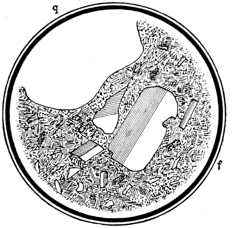
Fig. 18.—Sanidine crystal f, showing Carlsbad twin (which, as it consists of two parts only, may be called simple), and quartz q in rhyolite. Crossed nicols.
Structure:
(a) Twinning, generally noticed by the parts of the twin not
extinguishing at the same time. It may also be observed, without
crossed nicols, just as in the case of macroscopic minerals.
Twinning may be described as: simple, Fig. 18; polysynthetic,
due to repeated twinning after the same law, Fig. 12; and crossed
or “gridiron,” due to repeated twinning after two laws, Fig. 19.
38
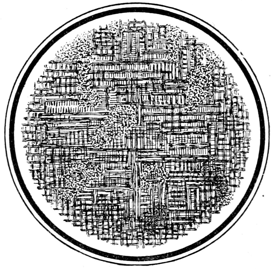
Fig. 19.—Microcline, showing crossed or “gridiron” twinning. Crossed nicols.
(b) Zonal structure, often only made visible by the zones extinguishing
at different times. It may, however, be noticed by the
zones being of slightly different color, or by the zonal distribution
of inclusions. In the case of the feldspars the zonal structure may
be caused either by the crystal being formed of zones of different
chemical composition (the successive zones in the plagioclases
growing more acid towards the exterior), or by ultra-microscopic
twinning,[67] Fig. 20.
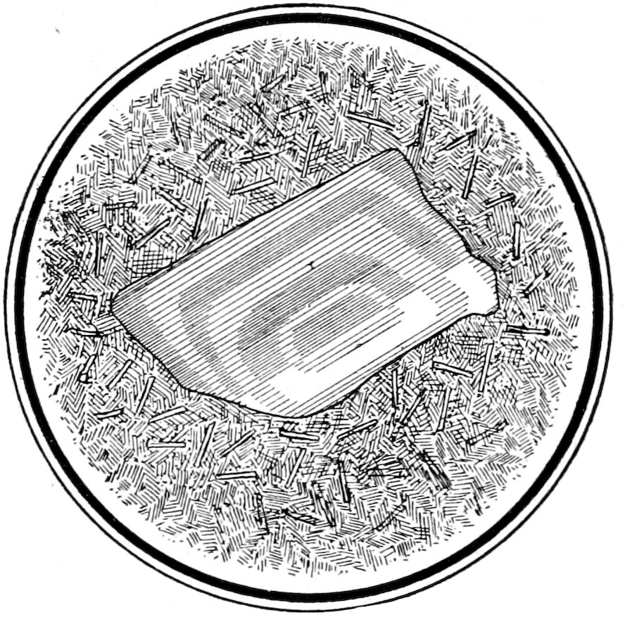
Fig. 20.—Zonal feldspar (Carlsbad twin) in trachyte. Crossed nicols.
(c) Aggregate structure, being a confused mass of separate little
39crystals, scales or grains all extinguishing at different times, Fig. 21.
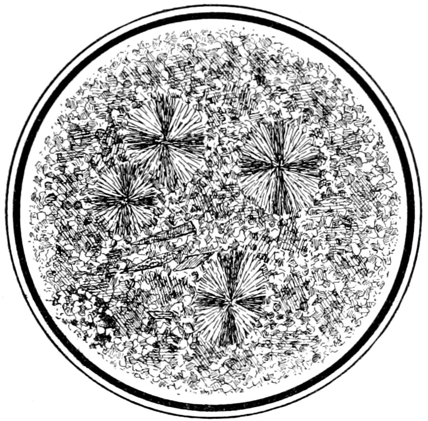
Fig. 21.—Sphærulites in felsite. Ground mass shows aggregate structure. Crossed nicols.
(d) Sphærulitic structure, produced by the aggregation, in a
radiate form, of crystals or crystallites. It is generally easily perceived
by the dark cross, resulting from the extinguishing of the
light in those crystals whose directions of vibration are parallel to
the planes of vibration of the nicols. When the stage is revolved
the arms of the cross do not rotate, Fig. 21.
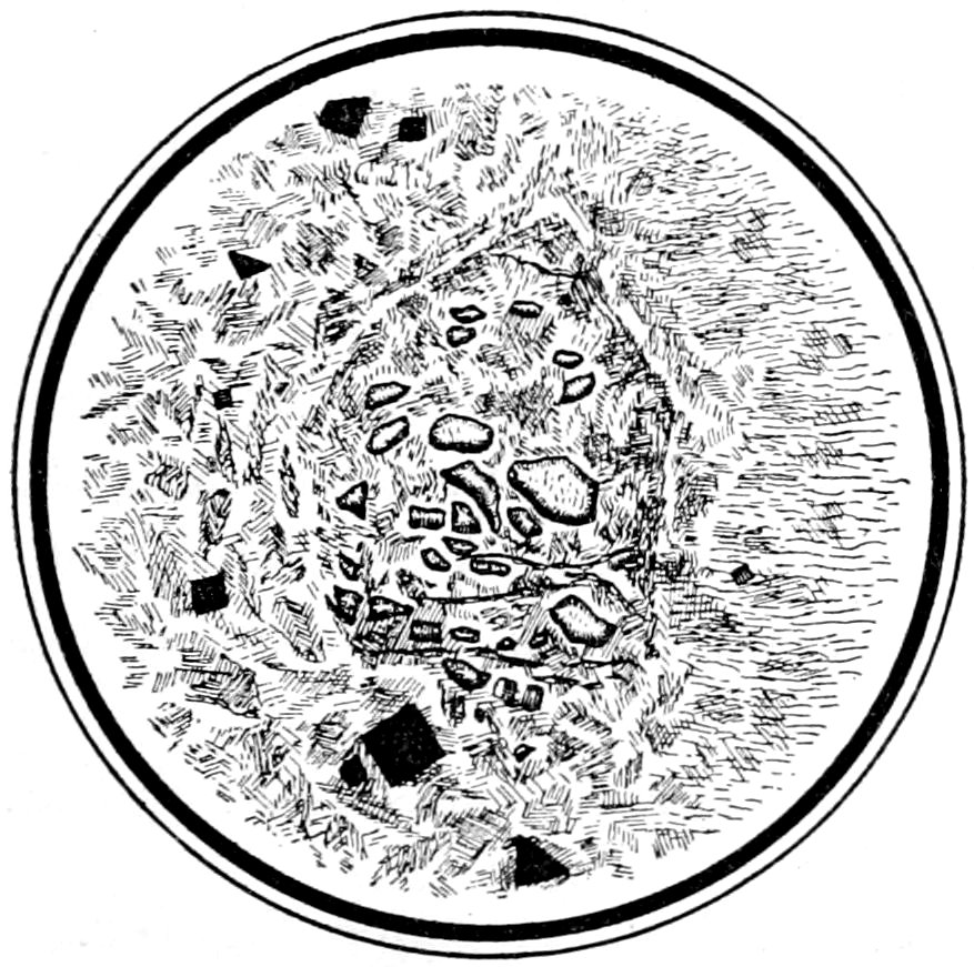
Fig. 22.—Olivine decomposed to serpentine. The pseudomorphism has been almost complete, only small portions of the original olivine remaining. The outline of the parent crystal can be quite distinctly seen. Crossed nicols.
(e) Pseudomorphic structure, which may be partial or complete
and is noticed by the changed portions producing different optical
40effects from those of the original mineral. Sometimes, although
the pseudomorphism has been almost complete, the form of the
original mineral or crystal may still be seen, Fig. 22.
Characters Observed by Convergent Polarized Light.
Convergent light is obtained by passing the rays of polarized
light through a strong condensing lens, which generally fits like a
cap over the top of the polarizer. By means of a suitable adjustment
the condensing lens can be brought very close to the lower
surface of the section on the stage. The lens thus sends a cone
of light through the section, and used in connection with crossed
nicols a series of optical phenomena, called interference figures,[68]
are produced.
Each direction in which rays are sent is traversed by a minute
bundle of parallel rays and these rays extinguish and produce
interference colors as already described for parallel light. Hence
each direction yields a spot or picture in the field of view and from
all these spots combined there results an “interference figure” or
picture, depending upon the structure of the section for all the
directions traversed by the rays.
A very high power objective[69] must be used, and when the eye-piece
is removed, a small image of the interference figure will be
seen. In some microscopes an arrangement is made for getting a
magnified image of the interference figure, by retaining the eye-piece
and using an additional Bertrand lens.
In order to get good results care must be taken to have strong
illumination and the condensing lens close up under the section.
The tests are best made with monochromatic light, but with white
light the effects are substantially the same, the only difference
being that the rings and curves are variously colored instead of
being simply light and dark.
Isotropic substances show no interference figures.
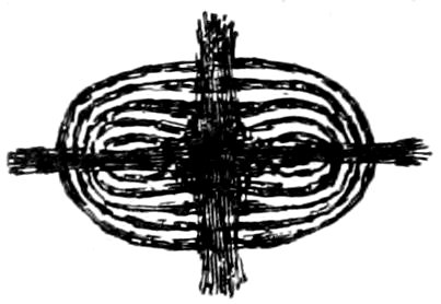
Uniaxial Interference Figures.
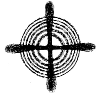
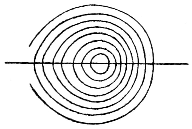
(a) Sections perpendicular to the optic or vertical axis ć show a
dark cross, with or without colored rings, Figs. 23 and 24. The
41figure is symmetrical to the center, as the optical behavior of uniaxial
crystals is symmetrical to the optic axis.
The arms of the cross are parallel to the planes of vibration of
the nicols, and the figure does not move when the stage carrying
the section is rotated.[70]
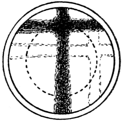
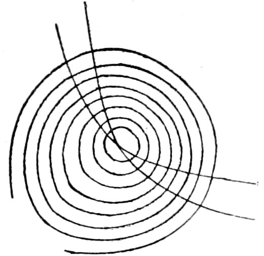
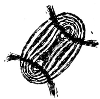
(b) Sections oblique to the optic axis show a portion of a dark
cross, with or without colored rings, Fig. 25. The centre of the
cross is not in the axis of rotation, and as the stage bearing the
section is revolved, the centre of the cross describes a circle, the
arms always maintaining parallel positions.
If the section is still more oblique to the optic axis the centre
of the interference cross may be outside the field of view, and only
portions of the dark arms will be seen.
Sections parallel to the optic axis show
a vague dark cross, which, on rotating the
stage, dissolves into hyperbolic curves
(suggesting biaxial figure), which very
rapidly disappear in the direction of the
optic axis. When the interference figure
shows colors, these colors are lower in
order in the quadrants containing the
optic axis. Knowing thus the position of the optic axis the
optical character can be obtained by the method for parallel light,
p. 43.
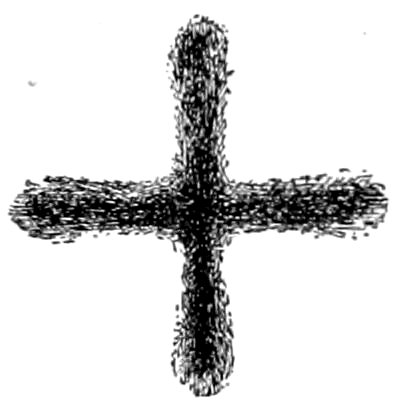
Sections which are thick and have strong double refraction will
show the cross and rings clearly and sharply defined, there being
quite a number of rings crowded close together. Sections which
42are very thin and have weak double refraction show only a broad
dark cross and no rings. The interference figures will vary between
these extremes, depending on the thickness of the section
and the strength of the double refraction.
To obtain the most characteristic figures, observations must be
made on sections about perpendicular to the optic axis, that is
sections which remain dark or nearly dark during complete rotation
between crossed nicols in parallel light.
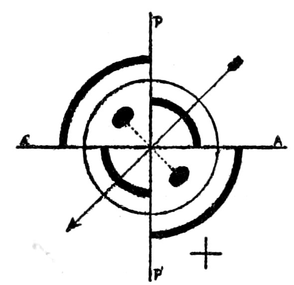
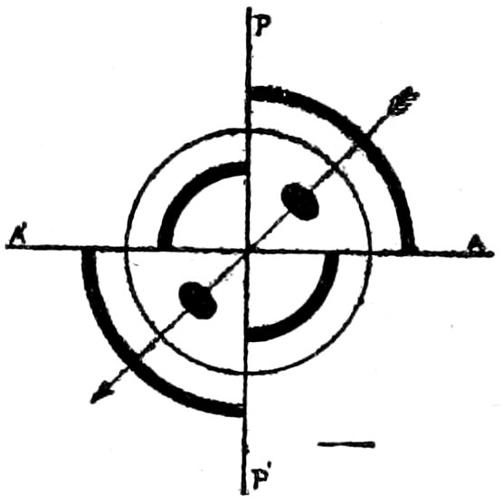
Optical Character, Positive or Negative. After having obtained
an uniaxial interference figure, test it by means of a ¼ undulation
mica plate. This plate must be introduced between the objective[71]
and the analyzer in such a way that its vibration direction c,
marked on the plate, makes an angle of 45° with the planes of
vibration of the nicols.
When this is done the interference figure changes, or may more
or less disappear, two dark spots or blotches being brought prominently
into view. If rings are still seen it will be noticed that
they have expanded in the quadrants occupied by the dark spots,
and have contracted in the remaining quadrants. This movement
of the rings may make it possible to determine the optical
character of a section, which is so oblique to the optic axis that
the dark spots are not seen after the introduction of the mica plate.
If the optical character is positive the line joining these dark
spots is perpendicular to the direction c of the mica plate, see
Fig. 26.
If negative the line joining the dark spots coincides with the direction
c of the mica plate, see Fig. 27.
43The (+) and (−) character is easily determined by remembering
that the line, joining the dark spots, makes the + and − sign
respectively with the direction c of the mica plate. The direction c
of the mica plate (represented in the figures by an arrow) is of
course not seen, but its position must be borne in mind when making
this test. This test can be made with either monochromatic
or white light.
If the mica plate does not give satisfactory results, which will be
the case when the double refraction of the crystal to be tested is
very weak or when the section is very thin, use a selenite plate, cut
the proper thickness to give the red color of the first order.
This plate must be introduced with its vibration direction a
(previously determined) making an angle of 45° with the planes
of vibration of the nicols. Instead of the dark spots being seen
there will appear two blue and two red quadrants. The diagonally
opposite quadrants being of the same color.
In determining the (+) and (−) character consider the blue
quadrants as the equivalent of the dark spots in the preceding case.
This test must be made with white light.[72]
Biaxial Interference Figures.
(a) Sections perpendicular to an optic axis exhibit the interference
figures shown in Figs. 28 and 29, the curves being nearly
circular and a straight black bar bisecting these curves, whenever
the trace of the plane of the optic axes coincides with the vibration
44direction of either nicol. As the stage, carrying the section, is rotated
the bar changes into one arm of a hyperbola and back again
into a bar. This arm or bar will rotate in the opposite direction
to the motion of the stage.
As previously stated sections of biaxial crystals, perpendicular
to an optic axis, do not remain dark during rotation of the stage
between crossed nicols in parallel light. On the contrary these
sections remain uniformly illuminated.[73]
(b) Sections perpendicular to the acute bisectrix (see p. 5), exhibit
interference figures like those shown in Figs. 30 and 31.
Fig. 30 shows the appearance of the interference figure when
the plane of the optic axes is parallel to the plane of vibration of
either nicol, and Fig. 31 shows the appearance when this plane is
inclined 45° to the planes of vibration of the nicols.
As the stage, carrying the section, is rotated the dark cross
seems to dissolve into two branches of a hyperbola, which again
unite to form a cross.
In sections perpendicular to a bisectrix, with a large axial angle,
the figure will appear, during a rotation of 90° (in the direction of
the hands of a watch), as in Fig. 32, top row. When the section
is somewhat oblique to an “optic axis,” the figure appears as in
middle row; and when still more oblique, as in bottom row.
The black centres[74] of the small ellipses and the black hyperbolic
curves mark the points of emergence of the optic axes, and therefore
indicate approximately the size of the axial angle, 2E.
Sections in other positions, relative to the optic axes, give interference
figures less definite in appearance than those just described;
and the same conditions affect the appearance of all figures as in
45the case of uniaxial crystals. Very thin sections, of weak double
refraction, may only show indistinct dark crosses or hyperbolic
curves, without any ellipses.
The section perpendicular to the acute bisectrix, which gives the
most characteristic interference figure, cannot generally be recognized
except by an examination in convergent light. It is never,
however, the section giving the maximum interference color. The
interference colors in different sections, normal to the optical elements,
grade downward in the following order: (1) optic normal,
(2) obtuse bisectrix, (3) acute bisectrix, (4) optic axis. Sometimes
cleavage may furnish a clue as to the best section to test
as in Topaz and Mica, where the acute bisectrix is normal to the
cleavage.
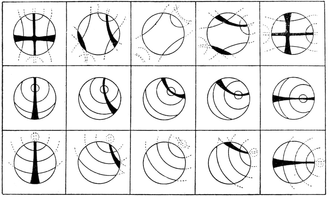
Fig. 32.—Biaxial Interference Figures (from Reinisch). Top row: Almost perpendicular to bisectrix, large axial angle. Middle row: Somewhat oblique to an “optic axis.” Bottom row: More oblique to an “optic axis.”
It must be remembered that this uncertainty, in the choice of
sections for testing, does not exist in uniaxial crystals; where the
best sections are indicated by the fact that they remain dark or
nearly so during complete rotation between crossed nicols.
The uniaxial or biaxial character of a mineral section, which only
shows an indistinct bar, may be determined as follows: A bar (one
arm of the cross) of a uniaxial interference figure moves in the
same direction as the rotating stage, and always remains straight,
46while the biaxial bar rotates in the opposite direction to the stage
and becomes curved.
Optical Character, Positive or Negative. When the axial angle
is very small, so that the interference figure approaches that of a
uniaxial crystal, the methods used for testing uniaxial figures are
employed.
When, however, the axial angle is large, the following method
can be used:
After having obtained an interference figure, from a section as
nearly at right angles to the acute bisectrix[75] as possible, the stage
is rotated until the plane of the optic axes (the trace of which on
the plane of the section is the line joining the points of emergence
of the two optic axes) makes an angle of 45° with the planes of vibration
of the crossed nicols or the cross-wires in the eye-piece.
A quartz wedge[76] is now pushed in between the mineral section
and the analyzer,[77] so that its axis ć = c (previously determined
and marked on the wedge) is either at right angles or parallel to
the plane of the optic axes of the mineral section.
The optical character of the mineral is positive when the ellipses,
surrounding the points of emergence of the two optic axes on the
convex sides of the hyperbola, appear to expand or open out
towards the centre when the quartz wedge is pushed in with its
axis parallel to the plane of the optic axes.
The optical character is negative when the ellipses appear to
expand or open out when the wedge is pushed in with its axis at
right angles to the plane of the optic axes.
As the ellipses expand they move from the points of emergence
of the optic axes towards the centre of the interference figure, and
47finally open into lemniscates which move outward from the plane
of the optic axes.
Even when the section is very thin and the double refraction
very weak, only the black hyperbolas without ellipses being seen,
the test can be made; and colored ellipses will appear, after the
pushing in of the quartz wedge, which will act in the same way as
the ellipses of the interference figure.
In a section at right angles to the obtuse bisectric these results
are all reversed.
When the section is perpendicular to one optic axis, rotate the
section until the plane of its optic axes is 45° to the planes of
vibration of the nicols. The interference figure will now have the
appearance as shown in Fig. 29, the hyperbola being convex
towards the acute bisectrix. Insert the ¼ undulation mica plate,
so that its direction c is parallel to the plane of the optic axes.
If the optical character is positive the hyperbola will move
towards the acute bisectrix and if negative away from it. When
the gypsum plate is used the blue color will appear on the convex
side for (+) and on the concave side for (−) minerals.
Determination of the Axial Angle.[78] This can be approximately
determined with a petrographical microscope, if equipped with a
micrometer eye-piece. Have the axial plane of the crystal section
in the diagonal position, Fig. 31; and measure the distance d
from the centre to either hyperbola with a micrometer (or average
the distance to both). Then sin E = d/C, in which C is a constant
for the same combination of lenses and is obtained by using
a crystal section (mica cleavage) of known axial angle. For
example, in a mica with 2E = 91° 50′ and d = 41.5 divisions on
the micrometer scale, C = d/sin E = 57.78 for that special combination
of lenses. The true axial angle can be obtained from the
equation sin V = d/βC.
48Optical Distinctions between Orthorhombic, Monoclinic, and
Triclinic Crystal Sections (perpendicular to acute and obtuse
bisectrices). The interference figures are always symmetrical in
shape and distribution of color to the planes and axes of symmetry
of the crystal system; hence are most symmetrical in the orthorhombic,
less so in the monoclinic and still less so in the triclinic
system.
Orthorhombic crystals show the figures always in two of the
pinacoids and in white light the color distribution will be symmetrical
to the trace of the axial plane and the line through the centre
at right angles to this trace and also to the central point.
Monoclinic crystals show the figures in the clino pinacoid or in
sections at right angles to this. In white light the color distribution
is never symmetrical to two lines, but is symmetrical either
to the trace of the axial plane (inclined dispersion[79]), or to the line
through the centre at right angles to this trace (horizontal dispersion),
or to the central point (crossed dispersion).
Triclinic crystals show in white light figures with distribution of
color unsymmetrical to any line or point.
In white light the “color fringes” of the hyperbola are due to
the “dispersion”[79] of the optic axes and bisectrices. That is, for
each color (for light of each wave-length) there is a particular
interference figure; the overlapping of these superposed figures
producing the color fringes.
When the axial angle is larger for red light than for violet, the
dispersion is said to be ρ > ν and the interference figure, in the
position of Fig. 31, will show the hyperbolic curves fringed with
red towards the centre (inside). In general the color with the
larger axial angle is nearer the centre of the field. This is due to
the extinguishing of light of each color at the axial points, the resulting
colors at these points being produced by white light minus
the absorbed color. When the dispersion is ν > ρ the reverse distribution
of color fringes will take place.
By measuring the axial angle in red and blue light, this dispersion
of the optic axes can also be obtained.
49
Resumé of the Uses of Parallel and Convergent Polarized Light.
Parallel light is used to detect pleochroism, to distinguish between
isotropic and anisotropic substances, to study interference
colors, to determine the strength of the double refraction, to locate
directions of vibration, to measure extinction angles, to find
the directions of vibration of the faster and slower rays, to determine
the relative value of the indices of refraction of the two rays,
and to investigate the crystal structure in general.
Convergent light is used to distinguish between uniaxial and biaxial
crystals, to determine whether a section that appears to be
isotropic is really so or only perpendicular to an optic axis and to
determine the optical character, grade of symmetry (system), axial
angle and dispersion.
51
CHAPTER IV.
The Microscopic and Optical Characters of Minerals.
OPAL.
Composition: SiO2.nH2O, generally soluble in caustic alkalies.
Usual Appearance in Sections: Colorless patches, incrustations or veins, also
at times with sphærulitic structure (hyalite), showing interference cross, of negative
character, between crossed nicols. Often shows anomalous double refraction
due to strains. The refractive index is very low (1.46) so that the surface of the
opal appears rough.
Remarks: Found as a secondary mineral in many acid volcanic rocks, rhyolite,
trachyte, andesite, etc., and also in basic basalts. H., 5.5 to 6.5. Sp. gr., 2.2.
LIMONITE.
Composition: Fe2(OH)6, Fe2O3, frequently quite impure.
Usual Appearance in Sections: Brownish and opaque, in very thin sections
may be translucent.
Remarks: Limonite is essentially a decomposition product, often forming
pseudomorphs after ferruginous silicates or halos about the iron ores.
PYRITE, Pyrites.
| Isometric. |
| Composition: FeS2. |
|
|
Usual Appearance in Sections: Cubes, pyritohedrons, combinations
of these forms; or in irregular grains. Outline of
cross-sections generally square.
Opaque, and by reflected light, bright yellow, with strong
metallic lustre.
Alters very easily to the oxides of iron (rust).
Remarks: May be present in all kinds of rocks, igneous, metamorphic and
sedimentary. Not noticeably acted on by hydrochloric acid. H., 6 to 6.5. Sp.
gr., 4.9 to 5.2.
PYRRHOTITE, Magnetic Pyrites.
Composition: FeS. Distinguished from pyrite by being practically always in
irregular masses and not in crystals, and by bronze yellow color with reflected
light. Found in basic eruptive rocks, more rarely in schists.
52
MAGNETITE, Magnetic Iron Ore.
Composition: Fe3O4, often contains Ti.
Usual Appearance in Sections: Grains and crystals (generally
octahedra), Fig. 33 B. Skeleton crystals frequent in highly ferruginous
eruptive rocks.
Twinning.—Common, according to Spinel law.
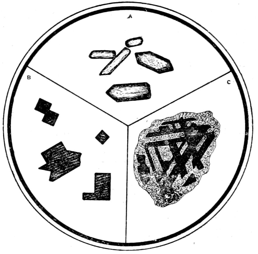
Fig. 33.—A, Zircon crystals (isolated from granite) in balsam, showing high relief. B, Magnetite crystals. C, Ilmenite, showing partial decomposition to leucoxene along crystallographic directions.
Opaque, and by reflected light, bluish-black, with strong metallic
lustre.
Distinguished from: Hematite, Chromite, Ilmenite and
Graphite, by being easily separated from powdered rock by weak
magnet.
Remarks: Very widely distributed in eruptive rocks and crystalline schists. In
the eruptive rocks magnetite belongs to the oldest secretions from the magma, immediately
followed by chrysolite, biotite, hornblende, augite, etc.; hence often
appears as inclusions in these and other minerals. Magnetite grains may form
with other substances pseudomorphs after hornblende, biotite, hypersthene, etc.
Such pseudomorphs appear to be caused by “resorption.” Magnetite is strongly
magnetic and soluble in hydrochloric acid. H., 5.5 to 6.5. Sp. gr., 4.9 to 5.2.
CHROMITE.
Composition: FeCr2O4.
Usual Appearance in Sections: Octahedral crystals, grains and in the olivine
53rocks sometimes in dense aggregates. May be surrounded by green, pleochroic
halo of chrome ochre.
Opaque, and by reflected light, brownish-black to black, with general absence
of metallic lustre. Usually translucent and brownish on the edges (by transmitted
light), with a very rough surface due to high index of refraction (n = 2.1).
Distinguished from:
(a) Magnetite by brownish-black to black color and general absence of metallic
lustre (by reflected light) and by grains being usually translucent and brownish
on the edges (by transmitted light).
(b) Spinel (Picotite), see under Spinel.
Remarks: Common in crystalline rocks, rich in magnesia, and in serpentine.
Chromite is not acted on by acids, is non-magnetic and gives chromium bead test.
H., 5.5. Sp. gr., 4.3 to 5.6.
SPINEL.
Composition: Mg(AlO2)2. Pleonaste (Fe, Mg spinel), Picotite (Cr spinel).
Usual Appearance in Sections: Octahedral crystals and twins (after spinel
law), less often in grains. Fracture cracks. Always optically normal and never
decomposed in rocks. Usually colorless or dark green (pleonaste) to brown (picotite).
The refractive index is high (n = 1.72, spinel proper, to 2.00, chrome spinel), hence
the relief is marked and the surface rough.
Distinguished from:
(a) Garnet when colorless by octahedral shape of crystals (garnet forms being
110 and 211), when brown (picotite) from melanite garnet by common zonal
coloration of the latter, but may require chemical tests. Furthermore spinel may
have green color and is never decomposed.
(b) Perovskite by the lower index of refraction and the absence of reaction
for Ti.
(c) Chromite chemically or by density or hardness.
Remarks: Found in gneiss, granulite, lherzolite and in regions of contact
metamorphism and secondary bedding formations (picotite), olivine-basalt and
serpentine. Spinels are insoluble in hydrochloric acid. H., 8. Sp. gr., 3.5 to 4.1.
GARNET.
Composition: R″3R‴2(SiO4)3. R″ is Ca, Mg, Fe or Mn; R‴
is Al, Fe‴, or Cr, rarely Ti.
Usual Appearance in Sections: Irregular grains, Fig. 13, or
simple crystals, showing forms (110) and (211), alone or in combination,
Fig. 14 b. Zonal structure not infrequent, especially in
the titanium varieties, Fig. 34.
Color.—Colorless, or nearly so, to yellowish, reddish or brownish.
Index of Refraction.—n = 1.750–1.856, hence relief high and
surface very rough.
Fracture.—Irregular cracks occur, but no cleavage noticed.
54Crossed Nicols: As garnets are isotropic, sections remain dark
during complete rotation. Optical anomalies may however occur,
but are generally confined to, titanium free, lime garnets and manganese
garnets. The effect being to divide the crystal symmetrically
into different areas, “dodecahedral structure.”
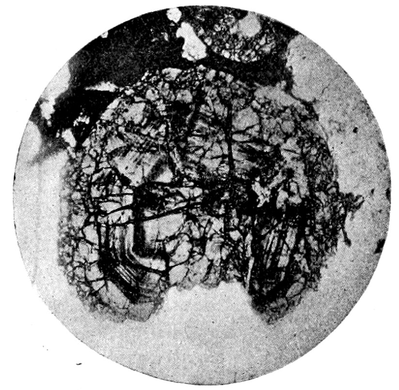
Fig. 34.—Garnet, with zonal structure, in gneiss. (From Cohen.)
Alteration: Garnets are usually fresh, but may be found altered
to chlorite or hornblende.
Distinguished from: Spinel and Perovskite.—See under the
latter.
Remarks: Found principally in granulites, metamorphic rocks, contact rocks,
crystalline schists, etc. Certain varieties may be found in eruptive rocks or olivine
rocks. May form pegmatitic borders with pyroxene, spinel, etc. Garnets are practically
insoluble in hydrochloric acid. H., 6.5 to 7.5. Sp. gr., 3.4 to 4.3. The insolubility
in acids and the high sp. gr. help in separating garnet from a powdered
rock.
LEUCITE.
| Isotropic. |
|
Isometric.[80] |
Composition: KAl(SiO3)2.
Usual Appearance in Sections: Crystals or grains, which vary
greatly in size. Cross-sections often nearly round. When very
55small and free from inclusions may be easily overlooked. Sometimes
the grains are surrounded by tangentially arranged needles
of different minerals.
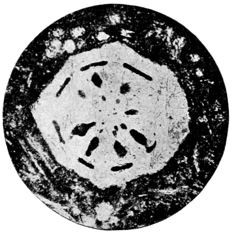
Fig. 35.—Leucite, with radial and tangential inclusions, Vesuvius Lava. (From Cohen.)
Color.—Colorless.
Index of Refraction.—n = 1.509, hence no relief and generally
smooth surface.
Fracture.—May be noticed, but no cleavage observed.
Inclusions.—Common, radially or zonally arranged, consisting
of minerals or glass, Fig. 35.
Crossed Nicols: The smaller crystals appear isotropic; the larger
crystals show characteristic intersecting systems of twin lamellæ,
Fig. 36.
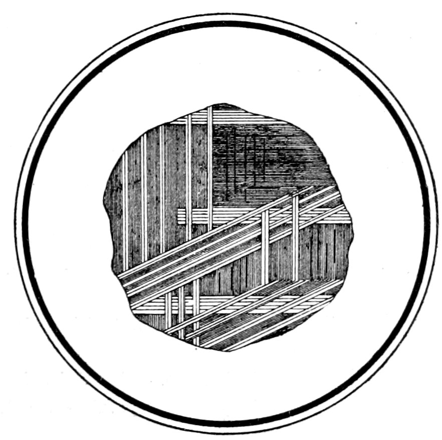
Fig. 36.—Leucite, showing complicated, interpenetration twinning between crossed nicols.
56Double Refraction.—Very weak (γ − α = 0.001). In thin sections
it may be necessary to use a sensitive color plate to prove
double refraction.
Interference Colors.—Very low 1st order, dark gray, etc.
Alteration: Quite frequent to fibrous or granular zeolites.
Distinguished from: Analcite—see under analcite.
Remarks: Almost entirely confined to younger eruptive rocks, phonolite,
tephrite and other leucite rocks and their tuffs. Often found with plagioclase,
nephelite, augite, etc. It is more or less attacked by hot hydrochloric acid. H.,
5.5 to 6. Sp. gr., 2.4 to 2.5. The isolation of leucite from rock powder can be
better accomplished by specific gravity than by chemical methods.
ANALCITE.
Composition: NaAlSi2O6 + H2O.
Usual Appearance in Sections: Secondary colorless grains, with no very characteristic
microstructure or properties. Cleavage parallel to cube (100) usually
seen. Index of refraction low (n = 1.488), hence rather rough surface. Between
crossed nicols may show optical anomalies, but not so marked as in garnet.
Distinguished from: Leucite, Sodalite and Nephelite. These minerals are
most easily confused with analcite and recourse must be had to chemical tests,
detection of optical anomalies, gelatinization test or turbidity by heating.
Remarks: Occurs as a secondary product (commonly from nephelite or leucite)
in alkali-rich eruptive rocks. Considered also as a primary mineral in igneous
rocks.[81] Gelatinizes with hydrochloric acid, and becomes turbid by heating. H.,
5.5. Sp. gr., 2.25.
SODALITE GROUP.
Sodalite, Haüynite (Haüyne) and Noselite (Nosean).
Composition:
Sodalite, 3NaAlSiO4 + NaCl.
Haüynite, 2(Na2Ca)Al2(SiO4)2 + (Na2Ca)SO4.
Noselite, 2Na2Al2Si2O8 + Na2SO4.
Usual Appearance in Sections: Dodecahedral rounded crystals or (S) irregular
grains. Colorless, yellowish, brownish, greenish to deep blue. Refractive
index low [n = 1.483(S) to 1.503(H)], hence the surface appears rather rough in
sodalite and slightly rough in haüynite. Inclusions, abundant and characteristic,
often rod-like and arranged regularly, making section translucent and especially
dark at border, Fig. 37. Dodecahedral cleavage sometimes seen. Optical anomalies
may occur.
Alteration: Takes place easily to aggregates of natrolite, other zeolites, mica, etc.
Distinguished from:
(a) One another only by chemical tests. Gelatinization test with hydrochloric
acid will show in addition to jelly, salt crystals for (S), abundant gypsum
57crystals (CaSO2 + 2H2O) for (H) and few if any gypsum crystals (absence of Ca)
for (N). (H) and (N) turn blue when heated, but test will not work if minerals
are decomposed. When treated with hydrochloric acid and nitrate of silver the
black sulphide of silver will show on (H) and (N), but the white chloride on (S).
(b) Nephelite (Elæolite) by being isotropic.
(c) Analcite by no turbidity when heated.
Remarks: These minerals are found in the basic, soda-rich rocks. (S) in elæolite-syenite
also in trachyte and phonolite, (H) and (N) common in phonolite and
leucite-porphyry. H., 5.5 to 6. Sp. gr., 2.3.
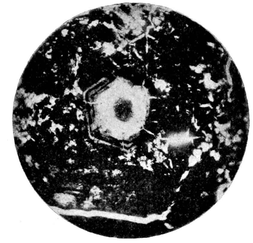
Fig. 37.—Haüynite, showing dark centre and border, in nepelinite. (From Cohen.)
PEROVSKITE, Perofskite.
| Isotropic. |
|
Isometric. |
| Composition: CaTiO3. |
|
|
Usual Appearance in Sections: Microscopic, octahedral crystals or larger
grains, pale brownish in color and not very transparent, darker colored in the
larger grains. In reflected light grains appear yellowish with adamantine lustre.
Refractive index very high (n = 2.38), hence relief very strong.
Between crossed nicols, the little crystals generally appear optically normal and
remain dark; but the larger crystals may show a complicated penetration twinning.
Distinguished from: Garnet (melanite) and Spinel (picotite) by much higher
refractive index and reaction for titanium and by zonal coloration of melanite. When
opaque it might be mistaken for the iron ores, but has no metallic lustre.
Remarks: Found in the younger basic eruptive rocks, especially melilite-basalt.
Commonly associated with the iron ores nephelite, augite and chrysolite. Insoluble
in hydrochloric acid. H., 5.5. Sp. gr., 4.1.
RUTILE.
| Anisotropic. |
Uniaxial. |
Tetragonal. |
| Composition: TiO2. |
ć = c |
Elongation ∥ ć. |
Usual Appearance in Sections: Sharp, elongated, prismatic crystals when
microscopic, but granular when the individuals are large. Grains may be almost
opaque, with adamantine lustre by reflected light. Knee- or heart-shaped twins,
58Figs. 38 and 39, common in the smaller crystals, the larger individuals may also
show geniculated twinning. Small crystals sometimes form net-shaped groups
(sagenite), by crossing one another at angles of 60°. Pleochroic halos may surround
crystals. Color, yellowish to reddish-brown. Index of refraction very high
(n′ = 2.712, α = 2.616, γ = 2.903), hence relief marked and surface very rough.
Prismatic cleavage present in larger individuals, not observed in microscopic crystals.
Pleochroism and strong absorption may be noticed, especially in the larger grains,
but may fail entirely.
Crossed Nicols: Double refraction very strong (γ − α = 0.287). Interference
colors[82] very high order, only seen in the microlitic crystals which do not appear
dark due to total reflection; in other cases may not show at all. Extinction parallel
to prisms. In convergent light optical character (+).
Alteration: May take place to a white or yellowish, fibrous or granular substance,
strongly refracting, and similar to the alteration product of ilmenite. May
be surrounded by grains of titanite.
Distinguished from: The Opaque Ores by adamantine lustre with reflected
light; Zircon and Cassiterite in concentrates by chemical tests. May not be
possible to distinguish from cassiterite in sections.
Remarks: Found in the metamorphic schists, amphibolites, slates, contact and
fragmentary rocks, etc.; also as inclusions in quartz and mica. Especially common
as a secondary product of titaniferous hornblende and biotite. The “sagenite”
webs of the decomposed micas are probably secondary. Rutile is insoluble
in hydrochloric acid. H., 6 to 6.5. Sp. gr., 4.2. It is easily separated from rock
powder by its insolubility in acid and its high sp. gr.
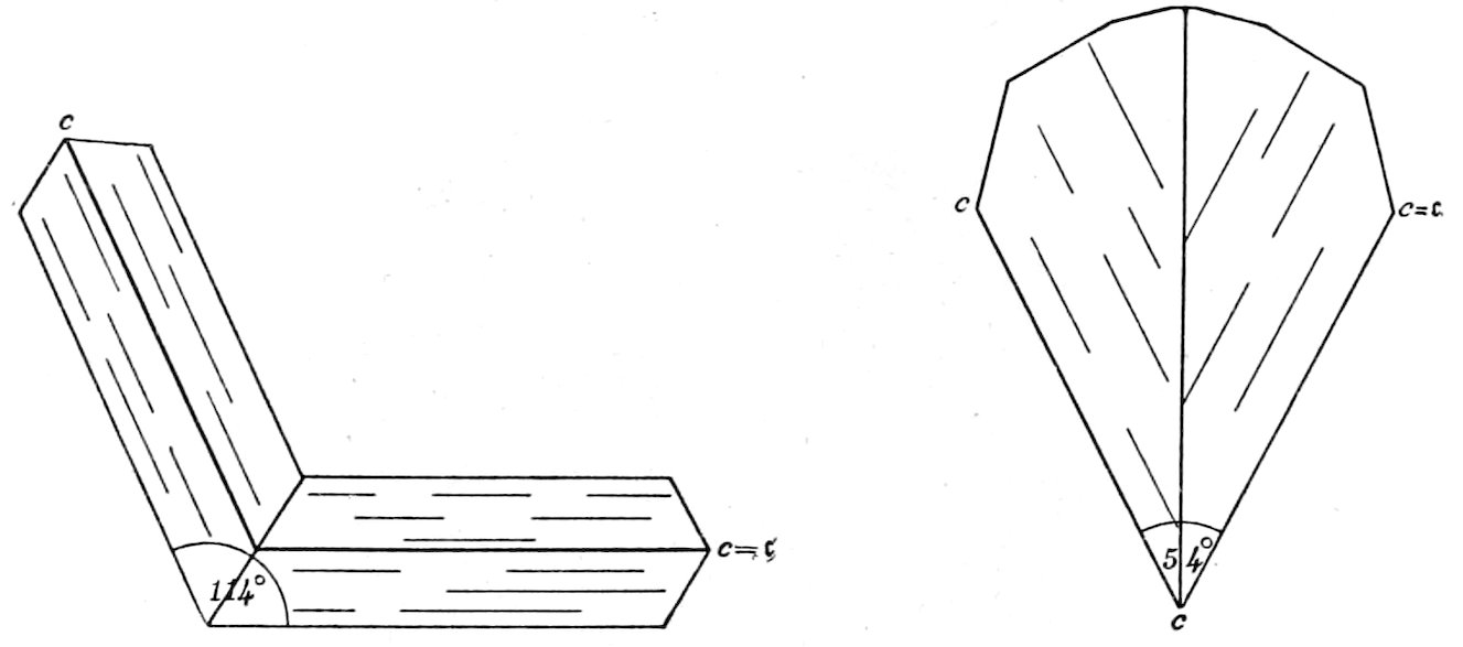
Rutile twins.
Fig. 38.—Twin plane (101). Fig. 39.—Twin plane (301).
ZIRCON.
| Anisotropic. |
Uniaxial. |
Tetragonal. |
| Composition: ZrSiO4. |
c = ć. |
Elongation ∥ c′. |
Usual Appearance in Sections: Small, short prismatic crystals,
Fig. 33A, and grains. Shell-like (zonal) structure may be noticed.
59When enclosed in black-mica, hornblende, cordierite, etc., often
surrounded by characteristic pleochroic halos.[83]
Color.—Colorless, rarely pale brownish.
Index of Refraction.—n′ = 1.95, (α = 1.931, γ = 1.993) hence
relief very high and surface rough.
Polarized Light:
Pleochroism.—Not usually noticeable.
Crossed Nicols:
Double Refraction.—Very strong (γ − α = 0.062).
Interference Colors.—Very high (4th) order, minute crystals
show brilliant colors.
Extinction.—As zircon is uniaxial, basal sections remain dark
during rotation of stage. In all other sections extinction is parallel
to ć.
Convergent Light: Basal sections, which are large enough to
give interference figures, show several rings in addition to dark
cross. Optical character (+).
Alteration: Very rarely takes place.
Distinguished from:
(a) Apatite.—By much higher relief and stronger double
refraction.
(b) Titanite.—By uniaxial character.
(c) Rutile.—See under the latter.
Easily confused with xenotime, which, however, has higher
interference colors and more distinct pleochroism; but chemical
tests may be necessary.
Remarks: Found widely distributed but not in quantity in eruptive and metamorphic
rocks. Occurs in granite, syenite, diorite, gabbro, gneiss, etc. It is one
of the oldest constituents of the rocks in which it occurs, and may often be found
as inclusions in the ferro-magnesium minerals. Zircon is insoluble in hydrochloric
acid. H., 7.5. Sp. gr., 4.5 to 4.7. It can easily be separated from rock powder
on account of its high sp. gr., insolubility in acid and non-magnetic properties. The
crystals can then be examined separately, or chemical tests made to prove the
presence of Zr.
SCAPOLITE GROUP, Wernerite, etc.
| Anisotropic. |
Uniaxial. |
Tetragonal. |
| Composition: Silicates of Ca, Al and Na. |
ć = a. |
Elongation ∥ a′. |
Usual Appearance in Sections: Colorless grains, lath-like individuals or
prisms (dipyre, in contact metamorphic limestone). Index of refraction
60(n′ = 1.551 to 1.584;, α = 1.542 to 1.558, γ = 1.555 to 1.597) about the same as
quartz, hence usually no relief and surface smooth. Cleavage distinct parallel to
square prism. Inclusions (carbonaceous) may be abundant in contact rocks.
Crossed Nicols: Double refraction usually strong, but varies (γ − α = 0.013
to 0.039), increases with the Ca percentage. Interference colors upper 1st or 2d
order, more brilliant than those of most of the colorless minerals. Basal sections
(showing cleavages intersecting at 90°) isotropic. Extinction parallel in
longitudinal sections. In convergent light basal sections show distinct uniaxial
interference figure; optical character (−).
Alteration: Takes place easily to a fibrous substance or to kaolin, muscovite, etc.
Distinguished from:
(a) Feldspars (not showing twinning) and Iolite (Cordierite) by uniaxial
character, cleavage and higher order interference colors.
(b) Quartz by cleavage, higher order interference colors and optical character;
quartz is (+)
(c) Apatite (in grains) by lower index of refraction, cleavage and higher order
interference colors.
Remarks: Found especially in metamorphosed diabases and gabbros (Norwegian);
also in gneisses, crystalline schists, metamorphosed limestones, etc.
Dipyre occurs in contact zones of limestones and schists, where it might be confused
with andalusite, but cross-sections show uniaxial character. The minerals
of this group are more or less soluble in hydrochloric acid. When the scapolite
contains Cl, the following test can be made on fresh material. Treat with a solution
of silver nitrate in hydrofluoric acid and the jelly will be impregnated with
chloride of silver which will turn brown. H., 5.5. Sp. gr., 2.68.
VESUVIANITE, Idocrase.
| Anisotropic. |
Uniaxial. |
Tetragonal. |
| Composition: Ca6Al3(OH.F)(SiO4)6. |
ć = a. |
Elongation ∥ a′. |
Usual Appearance in Sections: Grains or prismatic crystals. Almost colorless
to reddish (when containing Mn). Index of refraction high (n′ = 1.715,
α = 1.701 to 1.726, γ = 1.705 to 1.732), hence relief marked and surface rough.
Cleavage imperfect, parallel to prism. Pleochroism generally very faint.
Crossed Nicols: Double refraction very weak (γ − α = 0.001 to 0.006), may vary
in different portions of the same crystal (optical anomalies due to the mineral being
at times a mixture of isomorphous individuals). Interference colors very low
1st order, dark gray, etc., may often appear zonal. Basal sections isotropic when
normal, but may show division into biaxial portions. Extinction parallel in sections
elongated ∥ ć axis. In convergent light basal sections show a faint cross
when normal; optical character generally (−).
Alteration: Not known in rock-making vesuvianite.
Distinguished from: Epidote (Pistacite) by the very low order interference
colors. Corundum by weaker double refraction. Garnet (Grossularite), Zoisite,
and Apatite may be easily confused with this mineral and hard to distinguish
from it.
Remarks: Found in limestones, that have undergone alteration by contact with
igneous rocks, and in metamorphic schists. Also may occur in dense (nephrite-like)
aggregates in serpentine. It is insoluble in hydrochloric acid. H., 6.5. Sp.
gr., 3.3 to 3.8.
61
MELILITE.
| Anisotropic. |
Uniaxial. |
Tetragonal. |
| Composition: Na2(Ca,Mg)11(Al,Fe)4Si9O36?. |
| ć = a. |
|
Elongation ∥ c′. |
Usual Appearance in Sections: Almost colorless, tabular (∥ base) crystals or
irregular grains or shreds. Sections very commonly lath-shaped, and often characterized
by the peculiar “peg-structure,”[84] the lines or markings being ∥ ć (⟂
elongation of the section). Index of refraction (n′ = 1.630, α = 1.629, γ = 1.631)
higher than that of the other associated colorless materials, hence relief rather marked.
Cleavage, parallel to base, very imperfect.
Crossed Nicols: Double refraction very weak (γ − α = 0.003), and diminishes
with a decrease of Al. Interference colors the lower 1st order, grays, etc.; anomalous
interference colors may show. Extinction parallel to cleavage or the peculiar
markings or lines. Optical character usually (−), but when poor in Al (+).
Alteration: Takes place frequently to a fibrous aggregate.
Distinguished from: Nephelite and Feldspar by higher relief, shape, “peg-structure”
and usual dull appearance with reflected light.
Remarks: Abundant in the leucite and nephelite rocks (associated with these
minerals and with augite, perovskite and chrysolite), and takes the place of a feldspar
in the melilite-basalt. It gelatinizes easily with hydrochloric acid. H., 5.
Sp. gr., 2.9.
GRAPHITE.
Composition: C.
Usual Appearance in Sections: Minute particles, or flakes and grains of irregular
shape, seldom crystallized.
Opaque, and by reflected light, black with metallic lustre.
Distinguished from: The similarly appearing ores by its insolubility in acids
and the possibility of making it disappear by heating.
Remarks: Graphite is widely distributed in the oldest rock formations, especially
in the schists. It is often associated with rutile and the iron oxides.
Graphite is not acted on by acids. H., 1 to 2. Sp. gr., 2.09 to 2.25. It is burnt
with great difficulty in thin sections on platinum foil; but this test may vary, in
many cases the graphite (when in bladed flakes) not being consumed even after
long heating. When heated it may expand into worm-like forms.
Carbonaceous Matter.—Occurs in opaque, grayish-black particles having no
lustre; and is found finely disseminated, sometimes in larger aggregations, in
clay slates, limestones, etc.
HEMATITE.
Composition: Fe2O3.
Usual Appearance in Sections: Irregular scales, minute grains or earthy.
Distinct crystalline forms not often observed in rocks.
Opaque, and by reflected light, black with metallic lustre, or red without lustre.
May also be transparent in red tints. No marked pleochroism observed.
Remarks: Found widely distributed in acid eruptive rocks, crystalline schists,
etc. Also as inclusions in minerals, and as a red pigment in many rocks. It is
insoluble in hydrochloric acid, and non-magnetic, unless attached to grains of
magnetite. H., 5.5 to 6.5. Sp. gr., 4.9 to 5.3.
62
ILMENITE, Menaccanite.
Composition: (FeTi)2O3.
Usual Appearance in Sections: Irregular masses, without crystallographic
outline, rhombohedral crystals, or skeleton-like
growths. Also in brownish, translucent mica-like forms.
Opaque, and by reflected light, iron-black with metallic lustre.
When translucent: pleochroism brown to yellow; double refraction
not very strong; optically (−).
Alteration: Often takes place to a whitish, strongly refracting,
substance only slightly transparent, called leucoxene. This alteration
product frequently develops along definite rhombohedral directions,
Fig. 33 C. Also a change to titanite or rutile may occur,
or the ilmenite may be surrounded by these minerals.
Distinguished from: Magnetite and Hematite.—By whitish,
strongly refracting decomposition product. At times the distinction
may be very difficult.
Remarks: Ilmenite occurs principally in the soda-rich and basic eruptive rocks.
The mica-like form is limited to the porphyritic eruptives. The brown pigment in
the plagioclase of certain gabbros may be ilmenite. It is attacked slowly by hot
hydrochloric acid, and the solution when heated with tin becomes violet. Pure
ilmenite is indifferent towards the magnet, hence strong magnetic properties would
indicate a mixture with magnetite. H., 5 to 6. Sp. gr., 4.5 to 5.
CORUNDUM.
| Anisotropic. |
Uniaxial. |
Hexagonal. |
| Composition: Al2O3. |
|
c = a. |
Usual Appearance in Sections: Pyramidal or prismatic crystals, grains or basal
plates. Zonal structure or twinning may be noticed. Colorless or with patches
of blue. Index of refraction high (n′ = 1.766, α = 1.760, γ = 1.769), hence relief
well marked and surface very rough. Rhombohedral cleavage may show in larger
individuals. Pleochroism only marked when color is deep.
Crossed Nicols: Double refraction weak (γ − α = 0.009), like quartz. Interference
colors middle 1st order, white to yellow. Extinction parallel in elongated
sections. Optical anomalies very rarely noticed in microscopic individuals. In
convergent light basal sections show a rather indistinct cross; optical character
(−).
Distinguished from:
(a) Apatite and Vesuvianite by brighter interference colors.
(b) Tourmaline (light colored) by not having such strong absorption.
(c) Cyanite by uniaxial character.
Corundum may need to be isolated from the rock in order to be determined
with certainty.
63Remarks: found in contact metamorphic rocks, eruptive rocks, granular limestones,
etc. It is insoluble in hydrochloric acid. When rock sections are ground
with emery, care must be taken not to confuse grains of emery with corundum in
the rock. H., 9. Sp. gr., 3.9 to 4.
QUARTZ.
| Anisotropic. |
Uniaxial. |
Hexagonal. |
| Composition: SiO2. |
|
ć = c. |
Usual Appearance in Sections: Allotriomorphic in the granitoid
rocks, when apparently the last mineral to form, Fig. 5.
More or less chemically corroded pyramidal crystals (with cross-sections
six-sided or rhombic with an angle of about 100°) in the
porphyritic rocks. Rounded or angular grains in the “clastic”
rocks; granular mosaic in crystalline schists and contact rocks,
very rarely in distinct crystals in any rocks. May at times be
mutually interpenetrated with an acid feldspar (the areas of quartz
and feldspar extinguishing as entire crystals), producing “micro-pegmatitic”
structure, Fig. 67. Finally may appear as pseudomorphs
after other minerals, but may then consist of some of the
other forms of silica.
Color.—Colorless, although by reflected light it may appear
colored or cloudy if it contain many inclusions.
Index of Refraction.—n′ = 1.547 (α = 1.544, γ = 1.553) hence no
relief and surface smooth.
Cleavage..—Rarely noticed, an important fact in determining
quartz. Quartz breaks irregularly.
Inclusions.—Minute fluid, gas and mineral inclusions, often
in irregular trains, are very characteristic of quartz in granite rocks
and crystalline schists. The inclusions are not so abundant in
porphyritic rocks, but a few glass inclusions may occur, filling up
“negative” crystals in the quartz. Rutile, amphibole, etc., may
occur as needle-like inclusions in quartz.
Polarized Light:
Pleochroism.—None.
Crossed Nicols:
Double Refraction.—Weak (γ − α = 0.009).
Interference Colors.—The middle 1st order, white, yellow, etc.
Extinction.—As quartz is uniaxial, basal sections remain dark
during a complete rotation of stage. In the other sections extinction
64is not characteristic, due to the absence of cleavage and crystallographic
outlines. Thin sections do not show circular polarization.
Convergent Light: Basal sections show a dark cross, without
any rings. Optical character (+).
Alteration: Does not take place, so quartz always appears fresh
and unweathered in sections.
Distinguished from:
(a) Sanidine (in fresh grains).—By use of convergent light.
Feldspar is biaxial, or sections which appear uniaxial are (−).
(b) Nephelite.—By almost entire absence of hexagonal outline,
stronger double refraction, fresh, unweathered appearance
and (+) optical character.
(c) Iolite (Cordierite), Scapolite and Topaz.—See under the
latter minerals.
Quartz may be distinguished from all silicates by being dissolved
without residue in hydrofluoric acid.
Remarks: Quartz occurs widely distributed, as in the great sandstone formations.
It is also a characteristic mineral of all acidic rocks, being common in
granite, aplite, rhyolite, quartz-porphyry, quartz-diorite, dacite, etc. Quartz is very
brittle and hence is a good indicator of the dynamic forces which have affected
the rocks. It may show traces of mechanical deformation by peripheral shattering
of the larger grains or by “wavy extinction”;[85] and also evidences of chemical
corrosion by curved and looped contours. In some diabases the quartz may be
surrounded by a rim of hornblende or augite needles (“quartz augen”). “Cataclastic”
quartz may be biaxial. The “secondary enlargement” of quartz in clastic
rocks may be noticed by the deposition of silica in crystallographic orientation
around the clastic grains,[86] the new portion extinguishing at the same time as the
core. Quartz is not attacked by ordinary acids. H., 7. Sp. gr., 2.6 to 2.7.
Chalcedony.—This variety of SiO2 has a radially fibrous structure
and shelly parting. It may form sphærulites, central sections
through which show a dark cross between crossed nicols, or line
cavities in rocks.
The index of refraction is a little lower than for ordinary quartz.
The optical character is (−), which must be determined by a mica
or gypsum plate, ć = a. Elongation ∥ a′.
Chalcedony occurs in the ground mass of very silicious porphyritic rocks,
which have microfelsitic development; and is found as a secondary mineral in
all kinds of silicate rocks.
65
TRIDYMITE.
Usual Appearance in Sections: This form of SiO2, which is soluble in boiling
caustic soda, appears in “tile-like” aggregates of minute colorless plates (pseudo-hexagonal)
and is always secondary. The refractive index is extremely low
(n′ = 1.477), hence the surface appears rough.
Between crossed nicols the interference colors are very low in order (γ-α =
0.002), and the tablets may show a division into different areas (optical anomalies).
In convergent light an indistinct biaxial figure is generally seen.
Remarks: Chiefly a volcanic mineral, found in rhyolite, trachyte and andesite.
Commonly associated with opal and chalcedony.
CALCITE.
| Anisotropic. |
Uniaxial. |
Hexagonal. |
Composition: CaCO3. Ca may be replaced by small quantities
of Mg, Fe, Mn, etc. ć = a.
Usual Appearance in Sections: Grains and aggregates. May
be fibrous or oölitic. Only in crystals in certain rocks.[87]
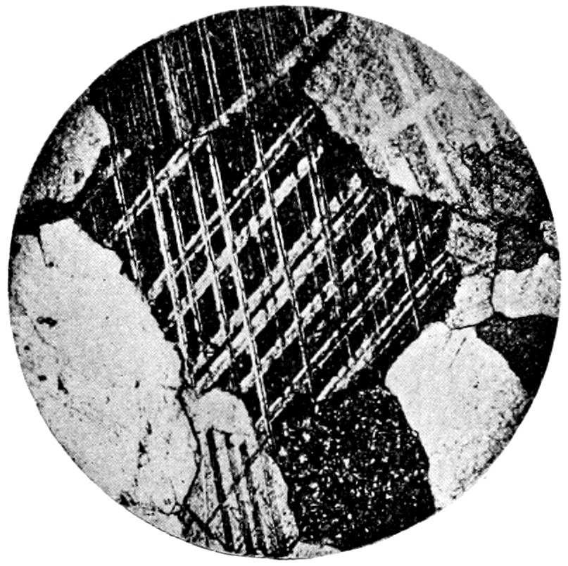
Fig. 40.—Calcite, crossed twin lamellæ, in granular limestone. (From Cohen.)
Twinning.—Polysynthetic, parallel to one or more faces of
−½ R. (10̄12). Very common in crystalline limestones, and may
have been produced by pressure or by the grinding of the section.
Shows itself between crossed nicols as a series of light and dark
bands, parallel or intersecting, Fig. 40, about parallel to longer
diagonal of cleavage rhombs. When the composition face of the
twins is oblique to the face of the section, interference colors can
be seen without the analyzer.
66Color.—Colorless when pure, but may appear colored by transmitted
light, due to organic pigments.
Index of Refraction.—n′ = 1.601 (α = 1.487, γ = 1.659) hence with
ordinary light relief not marked. Due to the great variation
in refractive indices of the two rays, with polarized light, the
surface will appear either quite smooth or rather rough, depending
upon which vibration direction lies over the plane of the polarizer.
This marked variation in appearance (sometimes called “twinkling”) serves as a good test for
calcite.
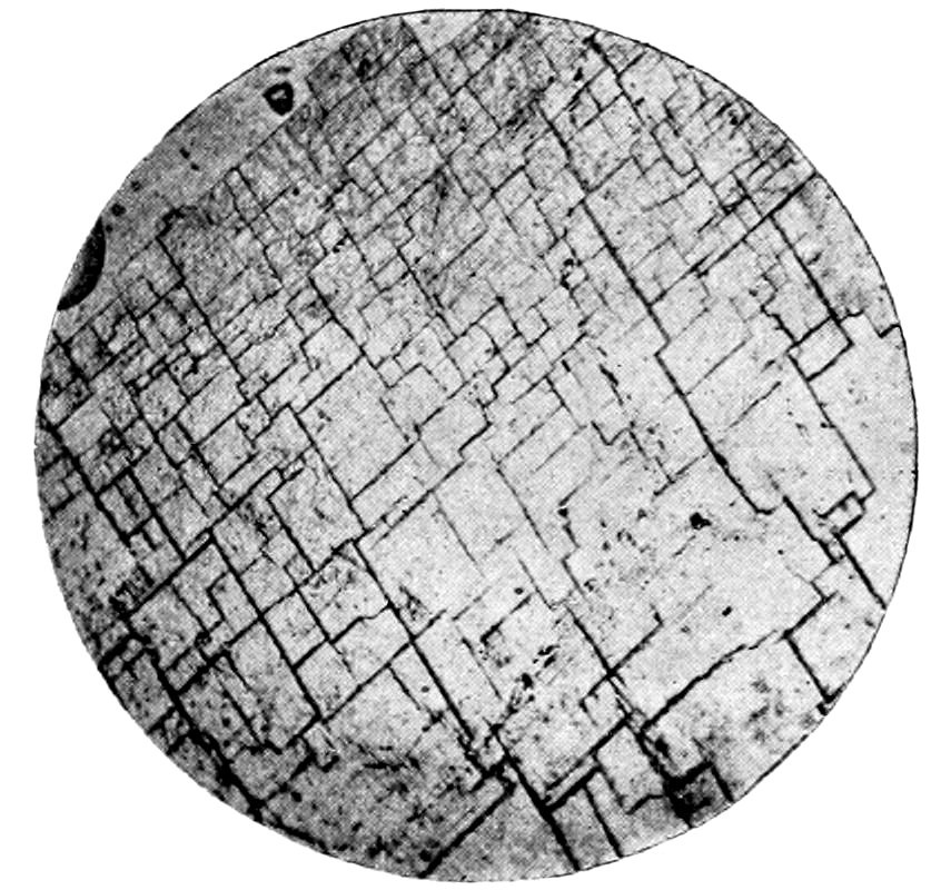
Fig. 41.—Calcite, section parallel to face of rhombohedron, showing rhombohedral cleavage. (From Cohen.)
Cleavage.—Parallel to unit rhombohedron (10̄11), appearing in
thin sections as many sharp cracks, whose angles of intersection
depend on the position of the section, Fig. 41. Newton’s colors
may be seen along cleavage cracks.
Polarized Light:
Pleochroism.—None.
Crossed Nicols:
Double Refraction.—Very strong (γ − α = 0.172).
Interference Colors.—Pale, iridescent colors of very high order.
Extinction.—As calcite is uniaxial, basal sections remain dark
during rotation. Extinction angles with respect to the cleavage
cracks vary with the position of the section.
Convergent Light: Basal sections, even when very thin, show
distinct interference figure, with cross and rings. Optical character
(−).
67Distinguished from:
(a) Other Carbonates.—By ease with which it is attacked by
cold dilute acids, test can be made on slide after removing cover.
(b) Magnesium-bearing Calcite.—By micro-chemical tests.
(c) Titanite (Sphene).—See under the latter.
Remarks: Calcite is very widely distributed, in addition to the extensive sedimentary
limestone deposits. Common limestone consists of dense aggregates of
crystalline grains. Calcite is often a secondary product of the lime-bearing silicates
in the more basic eruptive rocks. Pseudomorphs of calcite after olivine
are noteworthy. Coarse aggregates of calcite occur in the crystalline schists
and contact rocks. Calcite is exceedingly plastic to pressure and mechanical
deformation may be recognized by curving of the cleavage cracks, crumpling of
the twin lamellæ and “wavy” extinction. Calcite is easily attacked and completely
dissolved with effervescence by cold dilute acids. H., 3. Sp. gr., 2.72.
DOLOMITE.
| Anisotropic. |
Uniaxial. |
Hexagonal. |
Composition: CaMg(CO3)2, when pure CaO = 30.4, MgO = 21.7,
CO2 = 47.8. Proportions of Mg and Ca vary, and Fe and Mn also
occur. ć = α.
Usual Appearance in Sections: In rocks chiefly as crystals, even
dense homogeneous aggregates showing tendency towards crystalline
boundaries (saccharoidal structure). Crystals almost always
unit rhombohedron (10̄11) with tendency to curved surfaces.
Index of Refraction.—n′ = 1.622 (α = 1.503, γ = 1.682,
γ − α = 0.179), a little higher than that of calcite. For variation
in appearance of surface with polarized light, see under calcite.
The microscopic characters are similar to those of calcite, from
which it may be distinguished by not being so easily attacked by
cold dilute acid (test can be made on slide with cover off), by tendency
towards crystalline boundaries, by absence of twin lamellæ
(or when present parallel to −2R. (20̄21), hence about parallel to
shorter diagonals of cleavage rhombs), and by micro-chemical
tests. The distinction at times may be very difficult.
Remarks: Occurs in sedimentary formations and as crystals in limestone and
other rocks. In certain rocks the dolomite crystals may not have a very good
“bond,” and a “drusy” structure may also be characteristic of the cavities
between dolomite crystals in rocks. Only slightly attacked by cold dilute acids,
but if acid is heated it dissolves easily with effervescence.
68
APATITE.
| Anisotropic. |
Uniaxial. |
Hexagonal. |
| Composition: Ca5(Cl.F)(PO4)3. |
ć = a. |
Elongation ∥ a′. |
Usual Appearance in Sections: Minute, slender hexagonal
prisms, cross-sections having regular hexagonal boundaries,
needles, and grains. Figs. 14 a and 42.
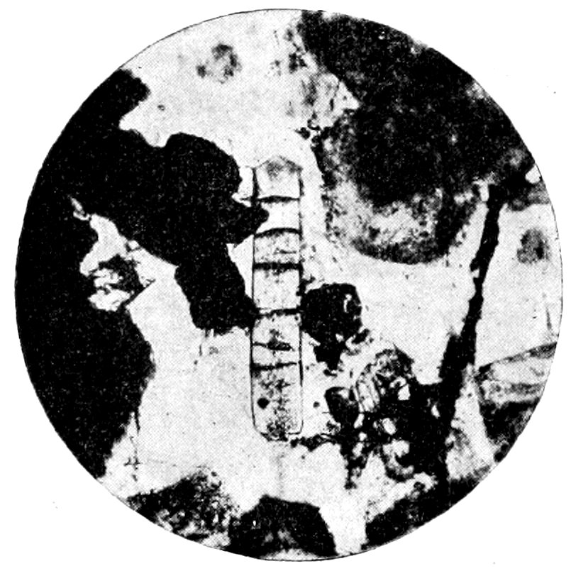
Fig. 42.—Apatite, showing cross fracture, in nepheline-basalt. (From Cohen.)
Color.—Generally colorless, seldom bluish or brownish (only
in eruptive rocks).
Index of Refraction.—n′ = 1.635 (α = 1.634, γ = 1.637), hence
relief more marked than that of the colorless associated minerals.
Cleavage.—Seldom observed microscopically.
Parting.—Long columnar crystals generally show a transverse
jointing, so that the pieces may be more or less separated.
Inclusions.—Gas and fluid may be present.
Polarized Light:
Pleochroism.—None shown by the colorless crystals, the colored
crystals show stronger absorption parallel to ć.
Crossed Nicols:
Double Refraction.—Weak (γ − α = 0.003).
Interference Colors.—The lower first order, generally grayish-blue
or white.
Extinction.—As apatite is uniaxial, basal sections remain dark
during rotation of stage. In all other sections extinction is parallel
to ć axis.
69Convergent light: Basal sections show a cross, without rings.
Optical character (−).
Alteration: Does not usually take place, apatite being found
perfectly fresh in decomposed rocks, which is quite remarkable
considering its easy solubility in acids.
Distinguished from:
(a) Sillimanite and Tremolite.—By weak double refraction
and elongation ∥ a′.
(b) Nephelite.—By being relatively much smaller and longer
than the nephelite crystals, which are often decomposed. Also by
higher relief and negative results with gelatinization test.
(c) Zircon.—By lower relief and much weaker double refraction.
(d) Feldspars (when granular and undecomposed).—By higher
relief and uniaxial interference figure.
(e) Vesuvianite and Zoisite.—May be only possible by chemical
tests.
(f) Corundum.—See under the latter.
Remarks: Found in most igneous rocks and crystalline schists. In the eruptive
rocks it appears as one of the oldest secretions from the magma, and hence is
often found as inclusions in other minerals, especially biotite, hornblende, etc.
Apatite is easily soluble in hydrochloric and nitric acids. H., 4.5 to 5. Sp. gr.,
3.19. On account of its high sp. gr., apatite, in rock powder, comes down in
heavy solutions with the metallic minerals, and can be separated from them by
the use of a magnet. This residue can also be tested for phosphorus in the wet
way with ammonium molybdate.
NEPHELITE,[88] Nepheline, Elæolite.
| Anisotropic. |
Uniaxial. |
Hexagonal. |
| Composition: 7NaAlSiO4 + NaAl(SiO3)2, with partial replacement of Na by K. |
|
ć = α. |
Usual Appearance in Sections: Nephelite in short hexagonal
prisms and grains in the younger volcanic rocks, hence sections
rectangular or hexagonal, Fig. 43; elæolite allotriomorphic in the
older plutonic rocks.
Color.—Colorless.
Index of Refraction.—n′ = 1.539 (α = 1.538, γ = 1.542), hence no
relief and surface smooth.
Cleavage.—Imperfect, parallel to prism (10̄10) and base (0001).
70More marked in elæolite than in nephelite, especially when decomposition
has commenced.
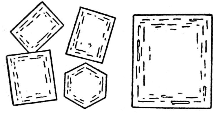
Fig. 43.—Nephelite sections, showing zonal inclusions. (From Reinisch.)
Inclusions.—Microscopic needles of augite, etc., also fluid and
gas. Mostly in zones. Elæolite may be much clouded by inclusions
and alteration products.
Polarized Light:
Pleochroism.—None.
Crossed Nicols:
Double Refraction.—Very weak
(γ − α = 0.004), may only be detected
by using a test-plate.
Interference Colors.—The
lower first order, grayish-white,
etc., a little lower than the feldspar
colors.
Extinction.—As the mineral is uniaxial, basal sections remain
dark during rotation of stage. In all other sections extinction
takes place and is parallel to cleavage lines when these appear.
Convergent Light: Basal sections show a broad cross, without
rings. Optical character (−).
Alteration: Takes place easily to fibrous zeolites (natrolite), or
in certain rocks to mica.
Distinguished from: Other Minerals by gelatinization test
and staining with fuchsine. When present in small interstitial
individuals (as is often the case in basalts) it is very difficult to distinguish
without this test; but it must be remembered that other
minerals, zeolites, etc., will also gelatinize. Quartz has stronger
double refraction, rarely shows hexagonal outline, is always fresh
and optically (+). Feldspar is biaxial and often shows twinning.
Analcite.—See under the latter.
Remarks: Nephelite bears the same relation to elæolite as sanidine does to
orthoclase. It occurs only in the younger volcanic rocks; with sanidine in phonolite,
with plagioclase in tephrite, without feldspar in nepheline-basalt, and with
leucite in leucite-basalt. It is not found with primary quartz. Elæolite occurs
with orthoclase in elæolite-syenite, etc. nephelite and elæolite frequently occur
with the sodalite group. Nephelite gelatinizes with acids. H., 5.5 to 6. Sp. gr.,
2.5 to 2.6.
TOURMALINE, Schorl.
| Anisotropic. |
Uniaxial. |
Hexagonal. |
| Composition: Uncertain, R18B2(SiO5)4. R chiefly Al, K, Mn, Ca, Mg, Li. |
ć = a. |
Elongation ∥ a′. |
71Usual Appearance in Sections: Staff-like individuals, bunched
or in radiating aggregates, Fig. 44 B, or prismatic crystals, Fig.
44 A. Basal sections may be nine-sided.
Color.—Varies greatly, grayish-blue, brown and green most common.
Li-tourmaline (rare in rocks) is colorless. Zonal structure
may be indicated by differences in color.
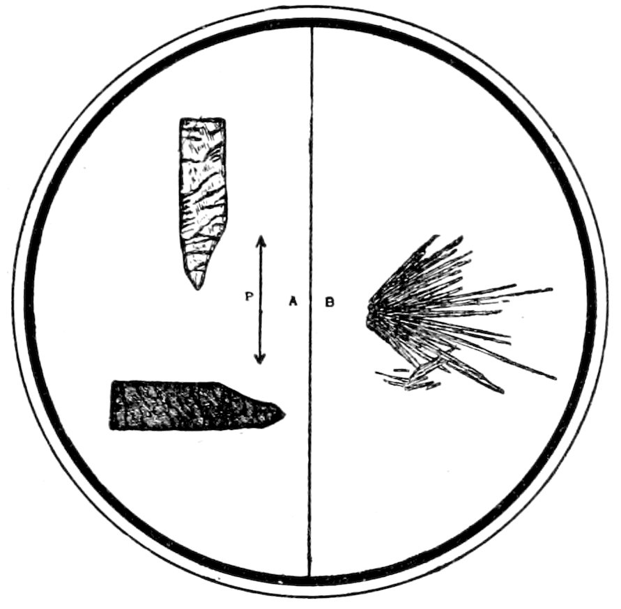
Fig. 44.—A, Tourmaline, showing strong absorption at right angles to direction of elongation (P = plane of vibration of polarizer). Quartzite, Black Hills, D. B, Tourmaline in radiate aggregate. Granite, Cornwall.
Index of Refraction.—n′ = 1.633 (precious) to 1.674 (α = 1.620 to
1.651, γ = 1.640 to 1.685), hence relief is marked and surface rough.
Cleavage.—Not seen in thin sections, but irregular, transverse
and longitudinal cracks may appear.
Polarized Light:
Pleochroism.—Distinct, even in light colored varieties, increasing
with the depth of color. The greatest absorption takes place at
right angles to the direction of elongation of the crystal, Fig. 44 A.
The other minerals having this very strong absorption are hornblende,
dark colored mica (distinguished by cleavage and lamellar
form) and allanite. Pleochroic halos may be noticed surrounding
inclusions.
Crossed Nicols:
Double Refraction.—Quite strong (γ − α = 0.017 (precious) to
0.034).
Interference Colors.—Bright upper first or second order, but
may not be noticeable, due to absorption of parts of the light.
72Extinction.—As tourmaline is uniaxial, basal sections remain
dark during rotation of stage. In all other sections extinction is
parallel to ć axis.
Convergent Light: Cross-sections show a sharp cross. Optical
character (−).
Alteration: Does not take place.
Distinguished from:
(a) Hornblende.—By absence of cleavage, and by the fact
that the greatest absorption takes place at right angles to the
longitudinal axis, while in hornblende it takes place approximately
parallel to the longitudinal axis, or to the cleavage lines which are
parallel to this axis.
(b) Apatite (when colored).—By strong absorption at right
angles to longitudinal axis.
(c) Corundum.—See under the latter.
In some cases where recognition is difficult, chemical tests, to
prove presence of boracic acid, must be made.
Remarks: The black schorl is the only primary tourmaline and is found in
granitoid rocks. Tourmaline in other rocks results from “fumarole” action;
hence occurs in pegmatite, tin and copper veins, clay deposits, also (light colored)
in contact rocks and crystalline schists. The hemimorphic terminations may
sometimes be noticed. Tourmaline is not acted on by acids. H., 7 to 7.5. Sp.
gr., 3 to 3.2. It can be separated from powdered rock by sp. gr. solutions combined
with magnetic methods.
ANDALUSITE
| Anisotropic. |
Biaxial. |
Orthorhombic. |
| Composition: Al2SiO5. |
ć = a. |
Elongation ∥ a′. |
Usual Appearance in Sections: In short, rounded, prismatic crystals, with
almost square cross-section. Colorless or at times pale reddish and spotted. Index
of refraction medium (n′ = 1.637, α = 1.632, γ = 1.643), hence relief well marked
and surface rough. Cleavage, parallel to almost square prism, may show. Pleochroism
only marked in colored varieties, being reddish ∥ ć (the direction of elongation
or cleavage). Carbonaceous inclusions are characteristic, arranged as in macroscopic
specimens (Chiastolite), Fig. 45. Pleochroic halos may surround inclusions.
Crossed Nicols: Double refraction weak (γ − α = 0.001). Interference colors
middle 1st order, white to yellow. Extinction in general parallel to ć axis in
longitudinal sections, symmetrical in cross-sections. In convergent light Ax. pl. ∥
(010), Bxa0. ∥ ć; axial angle very large (2E > 180°); optical character (−).
Alteration: Often takes place to dense aggregate of mica, when the pseudomorph
may be hard to recognize.
73Distinguished from:
(a) Sillimanite by much weaker double refraction, less elongated crystals
and by elongation ∥ a′ (Sillimanite elong. ∥ c′).
(b) Diopside by weaker double refraction, rhombic cross-section and parallel
extinction in longitudinal sections.
Remarks: Very characteristic of metamorphic schists and of contact zones of
clay slates with granite, etc., but not found in rocks which have been formed at
great pressure. The andalusite grains may often be arranged in divergent or
finger-like manner. May also form parallel growths with sillimanite. It is
insoluble in hydrochloric acid. H., 7 to 7.5. Sp. gr., 3.18.
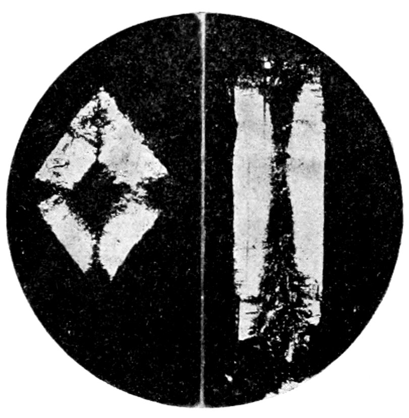
Fig. 45.—Chiastolite, showing characteristic carbonaceous inclusions. (From Cohen.)
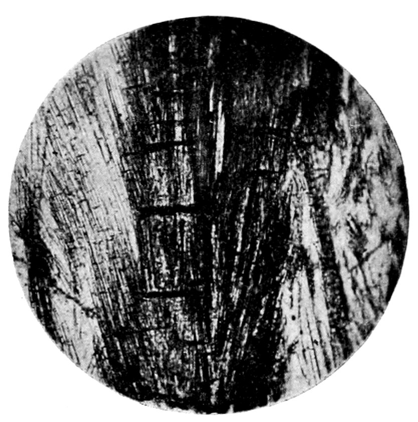
Fig. 46.—Sillimanite aggregate, showing cross fracture, in mica schist. (From Cohen.)
SILLIMANITE, Fibrolite.
| Anisotropic. |
Biaxial. |
Orthorhombic. |
| Composition: Al2SiO5. |
c = c′. |
Elongation ∥ c′. |
Usual Appearance in Sections: Long, slender, colorless prisms or needles;
often in felt-like aggregates. Crystals often bent. Index of refraction rather
high (n′ = 1.664, α = 1.656, γ = 1.677), hence relief marked. Transverse fractures
common, Fig. 46.
Crossed Nicols: Double refraction rather strong (γ − α = 0.021). Interference
colors upper first or lower second order, red, purple, blue, etc. Extinction
parallel to prisms. Ax. pl. ∥ (100), Bxa. ∥ ć, 2E = 35° to 55°. Optical character
(+).
Distinguished from:
(a) Apatite by higher order interference colors and by elongation ∥ c′ (apatite
has elongation ∥ a′).
(b) Tremolite by always parallel extinction and small size of axial angle.
(c) Andalusite, see under the latter mineral.
74Remarks: Found especially in clay-rich contact rocks, gneisses and schists,
often occurring with iolite (cordierite). Crystals may appear in bands. It is
insoluble in hydrochloric acid. H., 6 to 7. Sp. gr., 3.24.
TOPAZ.
| Anisotropic. |
Biaxial. |
Orthorhombic. |
| Composition: Al(Al(O.F2))SiO4. |
|
ć = c. |
Usual Appearance in Sections: Colorless crystals of short prismatic habit,
grains or rod-like radiating aggregates. Index of refraction about the same as
that of calcite (n′= 1.608 to 1.632, α = 1.607 to 1.629, γ = 1.618 to 1.637), hence
relief medium. Cleavage perfect, parallel to base, but does not show as many
cracks. Fluid inclusions abundant.
Crossed Nicols: Double refraction weak (γ − α = 0.008 to 0.011), about the
same as that of quartz. Interference colors middle first order, white, yellow, etc.
Extinction parallel to cleavage. In convergent light, Ax. pl. ∥ (010), Bxa. ∥ ć,
axial angle large (2E = 86° to 126°); interference figure obtained from basal
sections (i. e., from sections showing no cleavage); optical character (+).
Alteration: May take place to kaolin or muscovite, by loss of F and taking
up of H2O and alkalies.
Distinguished from:
(a) Quartz by higher relief, cleavage and biaxial character.
(b) Sillimanite (when topaz is in radiating aggregates) by lower refraction and
double refraction.
Remarks: Common in greisen and all granite rocks containing tin ore. When
formed by “fumarole” action (tin veins) the mineral shows rod-like radiating forms.
It is insoluble in hydrochloric acid. H., 8. Sp. gr., 3.5.
STAUROLITE.
| Anisotropic. |
Biaxial. |
Orthorhombic. |
| Composition: Fe(AlO)4(AlOH)(SiO4)2, but varying, may contain Mg or Mn. ć = c. |
|
Elongation ∥ ć. |
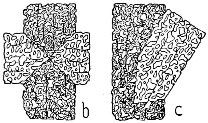
Fig. 47.—Staurolite, showing twinning at 90° b and 60° c, also granular quartz inclusions. (From Reinisch.)
Usual Appearance in Sections: Short, flat prisms, which may be twinned at
90° or 60°, Fig. 47, or grains. Color yellowish to reddish-brown. Index of refraction
rather high (n′ = 1.741, α =
1.736, γ = 1.746), hence relief marked
and surface rough. Cleavage, both
prismatic and pinacoidal, variable.
Inclusions of minute quartz grains and
carbonaceous matter found in larger
crystals, but not in microscopic crystals.
Pleochroism distinct but not
strong, showing red ∥ c (direction of
elongation). Pleochroic halos may
surround inclusions.
Crossed Nicols: Double refraction
weak (γ − α = 0.010). Interference
colors middle first order,
75white to yellow, etc. (about like quartz). Extinction in general parallel or symmetrical
(in cross-sections) to cleavages
or crystal outline. In convergent light,
Ax. pl. ∥ (100), Fig. 48. Bxa. ∥ć, axial
angle large (2E > 180°); optical character
(+).
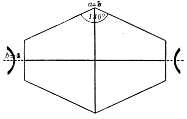
Fig. 48.—Staurolite, cross-section.
Alteration: Rarely takes place.
Distinguished from: Titanite, see
under the latter mineral.
Remarks: Found in metamorphic
schists, associated with cyanite (disthene),
iolite (cordierite), andalusite,
etc. It is one of the minerals produced by thermal metamorphism, hence found
in rocks of granite contact zones. It does not occur in the eruptive rocks or in
schists rich in amphibole. Staurolite is not acted on by hydrochloric acid. H.,
7 to 7.5. Sp. gr., 3.4 to 3.8.
THE ORTHORHOMBIC PYROXENES.
Enstatite and Hypersthene.
| Anisotropic. |
Biaxial. |
Orthorhombic. |
| Composition: (Mg.Fe)SiO3. |
ć = c. |
Elongation ∥ c′. |
Enstatite contains little, if any, Fe. Hypersthene contains more
Fe, its optical characters beginning to show with about 10 per cent.
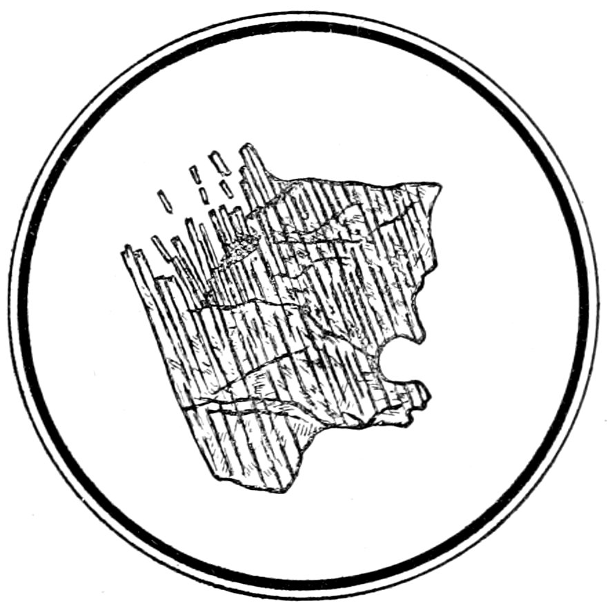
Fig. 49.—Enstatite, showing columnar or fibrous structure ∥ ć axis. Norite, Harzburg.
Usual Appearance in Sections: Irregularly bounded individuals
(E) or rounded prismatic-pyramidal crystals (H). Columnar or
fibrous structure ∥ ć often shows in (E), Fig. 49. Prism angle
about 92°. Outline of crystal sections very similar to that of
monoclinic pyroxenes.
76Twinning.—Not so common as in monoclinic pyroxenes. Parallel
growths with monoclinic pyroxene (diallage) occur.[89]
Color.—Varies with Fe per cent., (E) colorless, (H) brownish.
Index of refraction.—n′ = 1.665 (E) to 1.723 (H) (α = 1.660 to
1.716, γ = 1.670 to 1.729) (about the same as in monoclinic pyroxene),
hence relief marked and surface rough.
Cleavage.—Variable, parallel to prism (angle 92°) common to
all pyroxenes. Also cleavage or parting parallel to brachy pinacoid
(010) (prominent) and macro pinacoid (100).[89]
Inclusions.—Parallel oriented, brownish plates and rods, producing
“schiller” structure on the principal cleavage faces, Fig.
15. Glass inclusions abundant in (H).
Polarized Light:
Pleochroism.—Almost absent in (E), but distinct in (H), increasing
with Fe per cent. The change in color may be very
marked, from brownish-red to greenish ∥ ć.
Crossed Nicols:
Double Refraction.—Weak, much weaker than in the monoclinic
pyroxenes, increasing with Fe per cent. (γ − α = 0.010 (E) to
0.013 (H).)
Interference Colors.—Higher first order, about the same or a
little higher than quartz.
Extinction.—Parallel to cleavages in longitudinal sections, which
are parallel to a or b, and bisecting angles of intersecting prismatic
cleavages in basal sections.
Convergent Light: Axial plane parallel to brachy pinacoid
(010),[89] i. e., parallel to best pinacoidal cleavage. Bxa. ∥ ć (E),
∥ a(H). Axial angles large (2E = 95° to > 180°). Optical character
for (E)(+), for (H)(−). On account of weak double
refraction the interference figures are not very marked.
Alteration: Takes place to bastite, serpentine, etc.
Distinguished from: The Monoclinic Pyroxenes and Amphiboles.—See
under these species.
Remarks: Found in the granular rocks of the gabbro-peridotite series, also in
the olivine basalts (E); and in crystals in porphyritic andesite (H). These minerals
are in general not attacked by acids. H., 5 to 6. Sp. gr., 3.1 to 3.5.
Bronzite is the name give to the variety containing about 5% Fe and having
the characteristic bronzy lustre due to inclusions.
77Bastite (an alteration product of the orthorhombic pyroxenes
poor in Fe).—Composed of fibers, often traversed by irregular
cracks. Color light yellowish or greenish and index of refraction
about the same as Canada balsam. Pleochroism faint (only seen
in thick sections), the greatest absorption taking place parallel to
the fibers. Double refraction weak and extinction parallel to the
fibers. Axial angle large and axial plane at right angles to principal
cleavage face (010). The position of the axial plane is the surest
distinction between bastite and the orthorhombic pyroxenes.
CHRYSOLITE, Olivine.
| Anisotropic. |
Biaxial. |
Orthorhombic. |
| Composition: (Mg.Fe)2SiO4. |
Elongation ∥ a′ or c′. |
Usual Appearance in Sections: Prismatic crystals or in large
angular fragments or grains. Longitudinal sections more or less
lath-shaped, with pointed ends, Figs. 50 and 51, cross-sections six or
eight-sided. Outlines of crystals often rounded or corroded. Skeleton
forms may occur, and sometimes twinning may be observed.
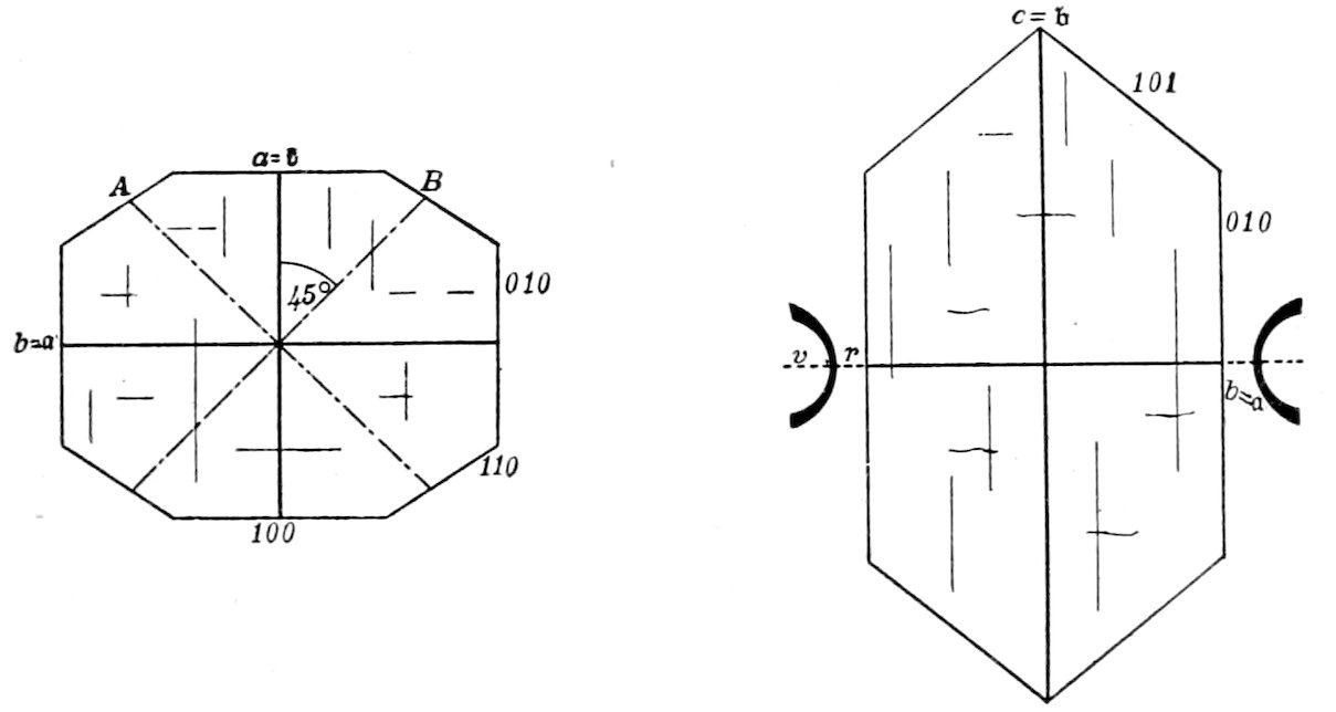
Chrysolite.
Fig. 50. Fig. 51.
Basal section. Macro pinacoid section.
Color.—Nearly colorless, may be reddish (with high Fe per cent.).
Index of Refraction.—n′ = 1.675 (α = 1.661, γ = 1.697), hence
relief marked and surface rough.
Cleavage.—Parallel to brachy pinacoid (010), less distinct parallel
to macro pinacoid (100), Fig. 50. Often only made visible by
decomposition. An irregular fracturing occurs, which increases
with alteration into serpentine.
78Inclusions.—Chromite, opaque earths, apatite and the brown
plates so common in hypersthene; also glass and slag (in basaltic
rocks) and fluid (in peridotites and olivinfels).
Polarized Light:
Pleochroism.—In general none, but noticed in the reddish varieties,
when the absorption is a little stronger parallel to ć.
Crossed Nicols:
Double Refraction.—Very strong (γ − α = 0.036).
Interference Colors.—Rather high in order (second or third),
higher than the colors of augite.
Extinction.—In general parallel to cleavage lines.
Convergent Light: Axial plane parallel to base (001) and
always at right angles to cleavage cracks, Fig. 51. Bxa. ∥ a.
Axial angle very large (2E > 180°). Optical character (+).
Alteration: Into serpentine very common,[90] producing “mesh-”
or “lattice-” structure (see under serpentine, p. 114); also into
amphibole, etc. In certain basaltic rocks the rims of grains may be
changed into gœthite?, and in certain gabbros the crystals may be
surrounded by a radial rim of amphibole.
Distinguished from:
Light colored Monoclinic Pyroxenes.— By the absence of extinction
angles, cleavage (the intersecting prismatic cleavages of
augite being of equal distinctness), stronger double refraction and
by axial plane being parallel to base, hence always at right angles
to best cleavage (in augite axial plane lies in clino pinacoid,
bisecting angles of intersecting prismatic cleavages). Also by
gelatinization with acids.
Remarks: Found only in basic rocks, as peridotite, diabase, gabbro, norite,
basalts, etc. Chrysolite (olivine) is a very brittle mineral and shows under mountain
making pressure “cataclastic” structure. Chromite is a characteristic associated
mineral. When not too poor in Fe, chrysolite becomes permanently red and
pleochroic when strongly heated. Chrysolite is decomposed by hydrochloric and
sulphuric acids, with separation of gelatinous silica. H., 6.5 to 7. Sp. gr., 3.3 to 3.4.
Hyalosiderite (a more ferruginous chrysolite) and Fayalite (Fe2SiO4)
may be reddish in sections, and common in the basic porphyritic
eruptive rocks.
IOLITE, Cordierite, Dichroite.
| Anisotropic. |
Biaxial. |
Orthorhombic. |
| Composition: Mg3(Al.Fe)6Si8O28. |
ć = a. |
Elongation ∥ a′. |
79Usual Appearance in Sections: Grains, more rarely crystals of short prismatic
habit, which often form pseudo-hexagonal interpenetration twins. Crystals may
have edges rounded or corroded. Colorless, but may be bluish. Index of refraction
a little lower than quartz (n′ = 1.539, α = 1.535, γ = 1.544), hence relief low
and surface smooth. Cleavage very variable, parallel to brachy pinacoid (010),
especially noticeable when decomposition has taken place. Inclusions of sillimanite,
zircon, rutile, etc., may be seen. Pleochroism usually not observed, but noticed in
blue sections (yellowish white ∥ ć to blue). Pleochroic halos (yellow) surrounding
inclusions common, see p. 59.
Crossed Nicols: Double refraction weak (γ − α =0.009), like quartz. Interference
colors middle first order, white to yellow. Extinction in general parallel
to cleavage cracks. In convergent light, Ax. pl. ∥ (100), Bxa. ∥ ć; axial angle
large (hyperbolas only seen without ellipses) (2E = 64° to 150°); optical character
(−).
Alteration: Takes place readily, forming greenish mica-like decomposition
products, the decomposition commencing along the crevices or about the inclusions.
Distinguished from: Quartz by observation in convergent light (quartz is
uniaxial), decomposition and pleochroism or pleochroic halos. The section can
also be treated with hydrofluosilicic acid, when the evaporated solution yields
characteristic prismatic crystals of magnesium fluosilicate.
Remarks: Found in gneiss, hornstone, granite, granulite, etc., and in some
volcanic rocks. It is often associated with garnet, biotite, sillimanite, etc. In
a thick section heating to redness makes the pleochroism more distinct. Iolite
is only slightly acted on by acids. H., 7 to 7.5. Sp. gr., 2.6. It is hard to make
a mechanical separation from quartz, on account of similarity in sp. gr.
NATROLITE.
| Anisotropic. |
Biaxial. |
Orthorhombic. |
| Composition: Na2Al2Si2O10 + 2H2O. |
ć = c. |
Elongation ∥ c′. |
Usual Appearance in Sections: Aggregates of colorless, fibrous crystals, which
may have sphærulitic structure, showing a dark cross between crossed nicols.
Index of refraction lower than balsam (n′ = 1.483, α = 1.478, γ = 1.490), hence (in
large crystals) the surface would appear rather rough.
Crossed Nicols: Double refraction weak (γ − α = 0.012). Interference
colors the middle first order (yellow, etc.), a little higher than those of quartz.
Extinction parallel to fibres. Optical character (+).
Remarks: Never a primary mineral in rocks, but found in igneous rocks filling
amygdaloidal cavities, and also as a very common alteration product of sodalite,
noselite, nephelite and acid plagioclases. It gelatinizes easily with hydrochloric
acid. H., 5 to 5.5. Sp. gr., 2.2.
OTHER ZEOLITES.
Composition: Hydrous silicates; Al, Ca and Na being the chief bases.
Usual Appearance in Sections: The form depends on the individual mineral
species, but the majority appear in elongated crystals or fibers. They are all colorless
and most of them have a small index of refraction, hence no relief (prehnite
has distinct relief).
80Crossed Nicols: The double refraction is generally very weak (between that of
nephelite and quartz), giving very low order interference colors (prehnite and
thomsonite have strong double refraction).
Remarks: The zeolites are always secondary minerals in rocks. They gelatinize
with hydrochloric acid.
GYPSUM.
| Anisotropic. |
Biaxial. |
Monoclinic. |
| Composition: CaSO4 + 2H2O. |
|
|
Usual Appearance in Sections: Colorless grains or fibers. May be colored,
however, by inclusions of carbonaceous matter, iron oxides, etc. Index of refraction
about the same as orthoclase (n′ = 1.525, α = 1.521, γ = 1.531), hence no relief
and surface smooth. Twinning lamellæ abundant. Cleavage parallel to (010) gives
abundant cracks, other cleavages may also be noticed.
Crossed Nicols: Double refraction weak (γ − α = 0.010), the same as quartz.
Interference colors middle first order, white to yellow. Extinction parallel to
most perfect cleavage cracks in sections parallel to b axis; large extinction angles
noticed with reference to less perfect cleavages. In convergent light, Ax. pl. ∥ (010),
i.e., ∥ to most distinct cleavages; Bxa. (c) Λ = 54° front; 2E = 104°; optical character
(+). As the characters of gypsum are not always very marked it may be necessary
to employ micro-chemical tests.
Remarks: Forms a rock by itself, often associated with rock salt. It also
occurs as an alteration product of anhydrite. Gypsum is soluble in hydrochloric
acid. H., 1.5 to 2. Sp. gr., 2.2 to 2.4.
MONOCLINIC PYROXENES, Augite, etc.
Including the monoclinic minerals of the Pyroxene Group, which show distinctly
the characteristic cleavage parallel to an almost right-angled prism.
| Anisotropic. |
Biaxial. |
Monoclinic. |
| |
Elongation ∥ c′.[91] |
|
Composition: RSiO3, R = Ca, Mg, Mn, Fe, Al chiefly, with the
Ca predominating over the Mg.
Usual Appearance in Sections: Both in crystals and more or less
irregular grains, Figs. 4 and 12, the habit varying with the chemical
composition as follows:
Diopside (Ca, Mg varieties), long columnar crystals and grains.
Augite (ditto, but containing also Al and Fe), short prismatic
crystals and grains.
Diallage, granular or lamellar (|| (100)), may show fibrous
structure ∥ ć.
Prism angle = 87° 06′ (important in cross-sections). Sections of
crystals nearly at right angles to the vertical axis ć are octagonal
81or square with truncated corners, Figs. 4 and 53, while those parallel
to the ć axis are lath-shaped. Pyroxene also occurs in skeleton
crystals and acicular microlites in eruptive rocks.
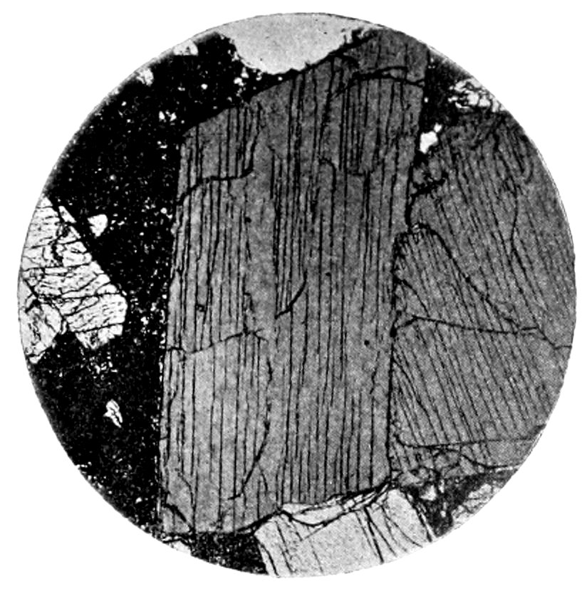
Fig. 52.—Augite, section parallel to ć axis showing prismatic cleavage, in leucite-basal. (From Cohen.)
Zonal structure (especially in augites) may be marked by differences
in color or extinction, and in some basalts the crystals have
the “hour-glass” structure.
Twinning.—Common, usually the twinning plane being the ortho
pinacoid (100). Twin lamellæ may be noticed. Intergrowths
occur with orthorhombic pyroxene and amphibole.
Color.—From almost colorless through green (diopsides, Na
pyroxenes, etc.) to brown (augites); the red to brownish-red color
of certain augites has been considered due to manganese. Yellow
color very rare.
Index of Refraction.—n′ = 1.68 to 1.72 (α = 1.671 to 1.706,
γ = 1.700 to 1.728), hence relief high and surface rough.
Cleavage.—More or less perfect parallel to prism of 87° 06′.
Cleavage cracks distinct and numerous, but not generally running
uninterruptedly through crystal, Figs. 12 and 52. Cleavage not so
perfect as that of amphibole.
Parting.—Diallage and diopside have distinct parting parallel to
ortho pinacoid (100), Fig. 53. Some crystals may show parting
parallel to base (001).
Inclusions.—Tabular microscopic interpositions, similar to those
82in bronzite, may occur in diallage. The iron ores, apatite, etc.,
may occur in augite.
Polarized Light:
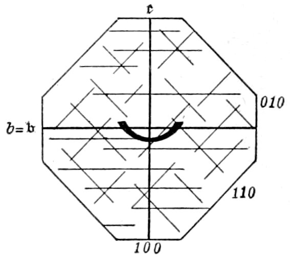
Fig. 53.—Diallage, cross-section.
Pleochroism.—Usually not noticed, and in general only appearing
as different shades of the same color. In some cases (diallage,
fassaite and Na rich augite) well marked, a and c green to
yellowish green and b brownish to
reddish-brown; hence pleochroism not
intense in sections showing extinction
angles. When Ti is present, violet parallel
to b.
Crossed Nicols:
Double Refraction.—Strong (γ − α = 0.022
to 0.029), being stronger in the
pale or colorless pyroxenes.
Interference Colors.—Second order,
hence always bright tints.
Extinction.—Symmetrical in sections (through b axis) showing
intersecting cleavage lines, in such cases bisecting the angles of the
cleavage. In sections showing parallel cleavage lines, only parallel
in ortho pinacoid (100) sections, in all other sections an extinction
angle being observed. The maximum extinction angle is large,
lies in the obtuse angle, varies with the chemical composition from
36° 30′ to 54°, and is only obtained when the section of the
crystal is parallel to the clino pinacoid (010), Fig. 54, varying
from this angle to 0°, when the section is parallel to the ortho
pinacoid (100). In Ti and Na pyroxenes the inclined dispersion
is so great that extinctions are not sharp, but instead a change takes
place in the interference color from bluish to brownish.
Convergent Light: Axial plane parallel to clino pinacoid
(010). Fig. 54. A cleavage flake parallel to ortho pinacoid
(100) shows the emergence of an optic axis (orthorhombic pyroxene
parallel to best pinacoidal cleavage would not show figure).
Bxa.(c) Λ ć = 36° to 54° front. Axial angles large (2E = 70° to
112°). Optical character (+). The interference figures are
distinct on account of the strong double refraction.
Alteration: May take place to chlorite, serpentine or amphibole
83(uralitization[92]), depending on the chemical composition and the
conditions producing the change.
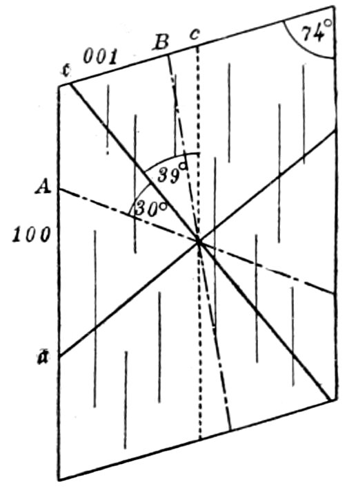
Fig. 54.—Diopside, clino pinacoid section.
Distinguished from:
(a) Orthorhombic Pyroxenes.—By extinction angle, the
orthorhombic pyroxenes having always parallel or symmetrical
extinction in sections parallel to a, b, or c, and by higher order
interference colors. Also from hypersthene
by absence of, or much fainter, pleochroism.
Diallage and bronzite might be confused on
account of pronounced pinacoidal parting,
fibrous structure and inclusions; but may be
distinguished by the presence or absence of
extinction angles and also by the position
of the optic axes relative to the best cleavage
plates.
(b) Amphibole.—See under amphibole.
(c) Epidote and Chrysolite (Olivine).
When light colored and granular, by examination
in convergent light. The plane of
the optic axes is parallel to the clino pinacoid (010), hence to
the longitudinal axis and prismatic cleavage cracks, while in epidote
it is at right angles to these directions and in chrysolite parallel to the
base. Also yellow color is common in epidote but rare in pyroxene.
Remarks: Next to the feldspars pryoxene is the most common constituent of
the igneous rocks. Diopside and fassaite (green) are found in contact rocks;
also, what appear to be the same pyroxenes, in many eruptive rocks, as andesites,
monzonites, etc. Malacolite (light green) is found in amphibolites and eclogites,
where it may be associated with a greenish amphibole (smaragdite). Diallage
(bladed and twinned) occurs in gabbros and pyroxenites. Common augite (brown)
is found in the remaining basic eruptive rocks. In the schists the pyroxene is
colorless.
Finally augite occurs as a secondary product resulting from the “magmatic
resorption” of hornblende and biotite.
Chemical corrosion and mechanical deformation may occur. The green and
brown augites when heated to redness on platinum foil may become red in color.
In general the pyroxenes are not attacked by acids. H., 5 to 6. Sp. gr., 3.3 to
3.5. The sp. gr. of the pyroxenes is considerably higher than that of the amphiboles
of similar composition, hence mechanical separations are possible.
Acmite (Ægirine) (Na pyroxenes).—Occur in green or brown,
elongated prismatic crystals, often not very transparent and with
84marked pleochroism (like amphibole). Zonal coloring is common.
When zonally intergrown with pyroxene the outer zone is ægirine.
The elongation is ∥ a′ (distinction from amphibole whose elongation
is ∥ c′). The index of refraction is higher than in the other
pyroxenes (n′ = 1.792, α = 1.763, γ = 1.813) and the double refraction
stronger (γ − α = 0.050). The extinction angle is small (5°)
and the optical character (—).
The term Ægirine-augite may be used to describe a soda, pleochroic
augite with a large extinction angle.
These pyroxenes are only found in the eruptive rocks rich in alkalies, as
elæolite-syenite, phonolite, certain trachytes, etc.; hence are associated with
elæolite, sodalite, leucite, etc. The small, second generation, crystals, in the
ground mass of a rock, are always the richest in Na of the pyroxenes in that rock.
AMPHIBOLE, Hornblende, etc.
| Anisotropic. |
Biaxial. |
Monoclinic. |
| |
Elongation ∥ c′. |
|
Composition: RSiO3. R = Mg, Ca, Fe chiefly also may contain
Al, Na, Mn. The Mg predominates over the Ca.
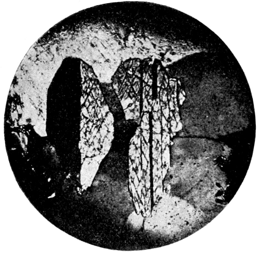
Fig. 55.—Hornblende, showing twinning between crossed nicols, in amphibole-biotite-granite. (From Cohen.)
Usual Appearance in Sections: Both in crystals and more or
less irregular grains, often fibrous, Figs. 55 and 56, the habit varying
with the chemical composition as follows:
Tremolite (Mg3Ca) and Actinolite ((MgFe)3Ca varieties), in
long columnar to needle-like individuals, with no terminal planes or
with frayed out ends. May be in dense aggregates.
85Pargasite in well developed crystals.
Common green Hornblende (aluminous varieties) in crystals,
compact grains or shreds.
Basaltic Hornblende (iron rich, aluminous varieties) in prismatic
crystals of varying length, which may often show “magmatic
resorption” (to augite and magnetite) around outer zone or
throughout whole crystal.
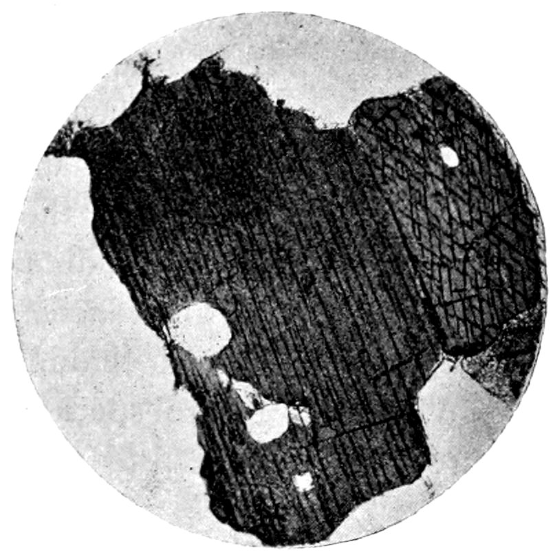
Fig. 56.—Hornblende, section parallel to ć axis, showing prismatic cleavage, in hornblende-diorite. (From Cohen.)
Crystals are simple in form of prismatic habit, with prism angle
124° 30′. Cross-sections are acutely rhombic, generally with acute
angles truncated, hence six-sided (pyroxene being eight-sided).
Longitudinal sections are lath-shaped and fibrous structure may be
noticed. Skeleton crystals may also occur, being very fine in certain
pitchstones.
Zonal structure and parallel growth may be noticed in the
amphiboles.
Twinning.—Frequent, parallel to ortho pinacoid (100). Twins
dual, less often multiple, Fig. 55. Intergrowths with pyroxene and
biotite occur.
Color.—From colorless (tremolite), through green (actinolite,
pargasite and hornblende) to brown (basaltic hornblende). Yellow
in some varieties and bluish in the soda varieties.
Index of Refraction.—n′ = 1.621 to 1.641 (α = 1.607 to 1.629,
γ = 1.634 to 1.653) (1.719, in the basaltic hornblende), hence relief
distinct and surface rough.
Cleavage.—Perfect, parallel to prism of 124° 30′. Generally
86appears in thin sections as sharp cracks crowded close together,
Figs. 56 and 57. More perfect than in pyroxene.
Some of the long prisms (actinolite and tremolite) may show
transverse parting.
Inclusions.—The iron ores, apatite, etc., may be found in hornblende.
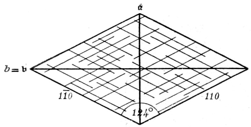
Fig. 57.—Hornblende, cross-section.
Polarized Light:
Pleochroism.—All colored amphiboles show pleochroism, which
in general is stronger the darker the color of the variety (actinolite
and pargasite show but little).
The absorption is very marked
in the hornblendes, being
greatest in the general direction
of the cleavage lines in
longitudinal sections. Marked
differences in absorption are
also characteristic of the mineral
species biotite, tourmaline
and allanite. Pleochroic halos (brownish) surrounding inclusions
may be noticed.
Crossed Nicols:
Double Refraction.—Quite strong, but a little weaker than in
pyroxene (γ-α = 0.019 to 0.027). Ferruginous basaltic hornblende
has strong double refraction (γ-α = 0.072).
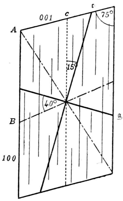
Fig. 58.—Actinolite, clino pinacoid section.
Interference Colors.—Second order, hence
bright tints, but in darker colored varieties
not so noticeable as in pyroxenes, due to
the stronger absorption of parts of the
light. The colors of basaltic hornblende
are so high that they show no bright tints.
Extinction.—Always symmetrical in sections
(through b axis) showing intersecting
cleavage lines, in such cases bisecting the
angles of the cleavage. In sections
showing parallel cleavage lines, only
parallel in ortho pinacoid (100) sections,
in all other sections an extinction angle
being observed. The maximum extinction
angle lies in the acute angle and is much smaller than in
87pyroxene, varying with the chemical composition from 0°–20°.
In hornblende, actinolite and tremolite 12°–20°, Fig. 58; in the
basaltic hornblende 0°–10°. The maximum extinction angle is
only obtained when the section of the crystal is parallel to the clino
pinacoid (010), varying from this angle to 0°, when the section is
parallel to the ortho pinacoid (100).
Convergent Light: Axial plane parallel to clino pinacoid (110),
Fig. 58. Bxo·(c) Λ ć = 0°–20° behind. Axial angles large
(2E = 77° to >180°). Optical character (−). Pargasite is (+).
Alteration: May take place to chlorite, talc, serpentine, asbestus,
etc., depending on the chemical composition. Amphibole
frays out and becomes fibrous during alteration, and may also lose
color.
Distinguished from:
(a) Pyroxene.—By usually much stronger pleochroism in the
colored varieties, and by cleavage and extinction angle. In pyroxene
the cleavage (parallel to prism of 87° 06′) is less perfect; and
the extinction angle is much larger, varying from 36° to 54°.
(b) Biotite.—By the extinction in the mica being always about
parallel to the cleavage. Both have strong absorption, but biotite
shows very slight pleochroism in sections parallel to the cleavage,
and has only the one cleavage parallel to the base. Also the biotite
has lower index of refraction and generally shows uniaxial interference
figure.
Colorless tremolite may be distinguished from muscovite and
talc by extinction angles, relief and lower order interference colors.
(c) Tourmaline.—By presence of cleavage, and by the fact
that absorption is most marked about parallel to the elongation
(also parallel to cleavage lines), while in tourmaline the absorption
is strongest at right angles to the elongation.
(d) The Orthorhombic Pyroxenes.—By extinction angles, the
latter having parallel extinction in all sections parallel to a, b and c,
and by prismatic cleavage of 124° 30′. Pleochroism is strong in
the colored varieties of both species, but in amphibole it appears
more generally as a variation of the same color; while in hypersthene
a change in color is often noticed, from brownish-red to
greenish parallel to ć axis.
(e) Sillimanite and Cyanite.—See under the latter.
88Remarks: Amphibole comes next to pyroxene in importance and distribution
of the dark colored ferruginous rock-forming minerals. As a rule it occurs in
rocks with a large percentage of SiO2, associated with quartz and orthoclase; while
augite generally occurs in rocks of a basic nature, associated with plagioclase and
little or no free SiO2. Furthermore amphibole contains hydroxyl and is therefore
naturally found in the deep eruptive rocks; its place being taken by augite in the
effusives. By application of heat hornblende changes to augite, while hydrochemical
processes bring about the opposite result “uralitization.”
Tremolite and actinolite are found in contact rocks and crystalline schists, also
as a result of the alteration of olivine into serpentine. Pargasite occurs in contact
rocks. Common green hornblende is found in the plutonic rocks (Na poor
and SiO2 rich), also in contact rocks and crystalline schists (amphibolites).
Brown hornblende replaces the green variety in the basic plutonic rocks. Basaltic
hornblende is found in many effusive rocks.
The hornblende crystals in eruptive rocks, being among the first formed constituents,
have often suffered subsequent corrosion by the magma, giving rise to
the dark border already mentioned. The brown primary hornblende in some
rocks may be changed by a process analogous to “uralitization” into a green,
reed-like hornblende. Mechanical deformations are found in massive and schistose
rocks. Light green amphiboles, with weak pleochroism, may often be colored
intensely reddish-brown and made strongly pleochroic by heating to redness on
platinum foil. In general the amphiboles are not affected by acids. H., 5 to 6.
Sp. gr., 2.9 to 3.3.
Glaucophane, Arfvedsonite, etc. (Na rich amphiboles).—Occur
blue to bluish-green in color, with pleochroism and weaker double
refraction than the other amphiboles. Extinction angles vary from
4°–6° (glaucophane) to 14° (arfvedsonite). They are found in
contact rocks, crystalline schists, eclogite, etc.
For the rarer and less known members of the amphibole group,
resource should be had to more elaborate works.
Uralite.—Pyroxene altered to amphibole, having the outward
crystal form of pyroxene and the physical characters and cleavage
of amphibole. The change usually commences on the surface and
the uralite does not form a single compact crystal, but consists of
numerous slender columns parallel to one another. These little
columns or fibers have their c and [=b] axes parallel to the positions
of these axes in the parent mineral. The color is green and the
pleochroism weak to strong.
This change is called “uralitization” and results from hydrochemical
processes. When the alteration is not complete, portions
of the original pyroxene may be left, having all the characteristic
optical properties of this latter mineral.
Anthophyllite, the orthorhombic amphibole, with always parallel
extinction, is sometimes found in colorless to brownish, blade- to
rod-like aggregates in crystalline schists and serpentine.
89
MICA GROUP.
| Anisotropic. |
Biaxial. |
Monoclinic. |
| May appear hexagonal or orthorhombic. |
| Composition: |
Elongation (∥ cleavage) ∥ c′. |
Biotite (black or ferro-magnesium mica) = (H.K)2(Mg.Fe)2Al2(SiO4)3,
approx.
Phlogopite = a magnesium mica, near biotite, but containing
little Fe.
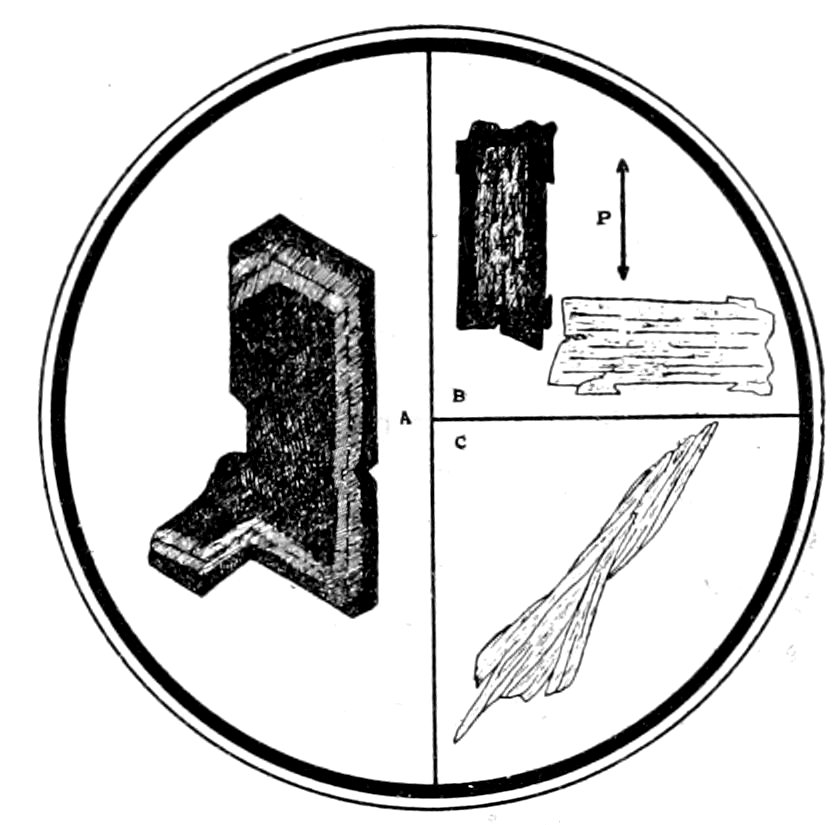
Fig. 59.—Mica. A, biotite, showing hexagonal cross-section and zonal markings. Minette, Freiburg. B, Biotite, showing strong absorption parallel to cleavage and also zonal marking (P = plane of vibration of polarizer). Minette, Cumberland. C, Muscovite in bent shreds in gneiss.
Muscovite (white or potash mica) = H2(K.Na)Al3(SiO4)3, with
some replacement by Mg or Fe.
Usual Appearance in Sections: Scales, which may be notched
or jagged, with lateral sections lath-shaped; or shreds, Fig. 59 C.
When distinctly crystallized (magnesium micas) the thin hexagonal
plates have plane angles of 120°, Fig. 59 A. Phlogopite crystals
may be extended in direction of ć axis.
Zonal structure not uncommon in the magnesium micas, Fig.
59 A, which may also have dark iron ore border like hornblende.
Twinning.—Common, generally parallel to base; seen in sections
showing cleavage by variations in extinction, in basal sections by
distorted interference figures.
Micas of different kinds often associated together in parallel position,
also intergrown with hornblende, pyroxene, chlorite and
quartz.
90Color.—Depends on chemical composition. Biotites, brown,
green or red to almost opaque. Phlogopites, colorless or yellowish.
Muscovites colorless.
Index of Refraction.—n′ = 1.564 to 1.619 (α = 1.541 to 1.580,
γ = 1.575 to 1.638), hence somewhat marked relief and surface
varies in appearance from slightly rough to fairly rough. In
polarized light the surface appears roughest when the cleavage
cracks are parallel to the plane of the polarizer.
Biotite has more marked relief.
Cleavage.—Very perfect, parallel to base (001), Fig. 60. Basal
sections show no cleavage, but all other sections show many sharp,
parallel cleavage cracks.
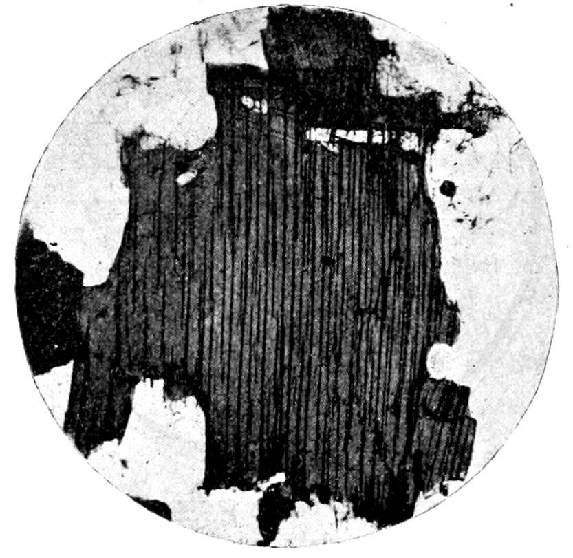
Fig. 60.—Biotite, showing basal cleavage, in biotite-granite. (From Cohen).
For percussion and pressure figures, see reference given below.[93]
Inclusions.—May be arranged parallel to lines of pressure figure.
Rutile needles, tourmaline, apatite, etc., common in magnesium
mica. Zircon inclusions often surrounded by pleochroic halos.
Polarized Light:
Pleochroism.—Varies with the color, being very marked in the
colored varieties (from pale yellow to chestnut-brown or black).
The strong absorption, about parallel to the cleavage lines, is very
characteristic of the colored mica, Fig. 59 B. Strong absorption
is also noticed in hornblende, tourmaline and allanite. Absorption
may even be noticed around inclusions (pleochroic halos) in colorless,
non-pleochroic micas. Cleavage plates of biotite are not pleochroic
unless the axial angle is large.
91Crossed Nicols:
Double Refraction.—Very strong (γ − α = 0.034 to 0.058).
Interference Colors.—High order (third). May be very bright
in thin sections of the colorless micas, and at times be so high in
order as not to show any marked color tints. May not be noticeable
in sections of the colored varieties, due to absorption of parts
of the light.
Extinction.—About parallel to cleavage lines. Very small extinction
angles may be noticed in biotites. Basal sections of biotite
(the approximately hexagonal mica) usually appear isotropic.
Mottled appearance (like “Birds-eye” maple) characteristic,
caused by distortion of the flexible laminæ during grinding. Most
noticeable in sections inclined to cleavage and near position of
extinction.
Convergent Light: Axial plane[94] and Bxa, practically at right
angles to basal cleavage; therefore cleavage plates always show
well defined interference figures, generally biaxial in character.
The axial angles vary greatly, being usually small for biotite and
phlogopite (may appear uniaxial) and large for muscovite (2E = 55°
to 90°). Optical character for all micas (−).
Alteration: Biotites decompose quite easily, lose color and may
become completely bleached, which appears to be due to a leaching
out of the iron. May also alter to green chlorite, with a fraying
out of the mica and a change to chloritic structure.
Phlogopites may alter to fibrous, scaly masses, apparently chiefly
talc. “Sagenite” webs of rutile may accompany the alteration.
Muscovites are characterized by their freshness, and do not seem
to suffer from weathering.
Distinguished from:
(a) Hornblende.—Magnesium mica has extinction about parallel
to the cleavage, while hornblende may have extinction angles
of from 0° to 20°. Both have strong absorption, but biotite shows
very slight pleochroism in basal sections, which also give approximately
uniaxial interference figures in convergent light.
(b) Tourmaline.—Magnesium mica shreds show absorption
parallel to elongation, while in tourmaline the absorption is at right
92angles to elongation. There is also an absence of cleavage in
tourmaline.
(c) Chlorite.—By strong double refraction, the very high
order colors, however, being often not noticed. Chlorite also
shows aggregate structure and is almost always greenish in color.
(d) Talc.—White mica by large axial angle of scales in convergent
light and by micro-chemical tests. The distinction may
be very difficult.
Remarks: Muscovite is a rare primary mineral in eruptive rocks, except in two-mica
granite, etc. As a secondary mineral it occurs in dense scaly aggregates or
as pseudomorphs after feldspar, nephelite, etc. It is frequent in crystalline
schists and is probably also the mica in amphibolite and eclogite. Phlogopite is
found chiefly in contact metamorphic limestone; and may be distinguished from
muscovite by nearly uniaxial character and less sharp cleavage. Biotite is much
more widely distributed, occurring especially in eruptive rocks, crystalline schists
and contact rocks.
Chemical corrosion occurs in original biotite of porphyritic rocks, producing a
“resorption border” of augite and magnetite. Mechanical deformations, producing
bending and slipping along “gliding” planes (oblique to cleavage), are
common to all varieties of mica and may produce change to chlorite. The muscovites,
together with the feldspars, are the most characteristic minerals of
dynamo metamorphic origin. Biotites and phlogopites are attacked by sulphuric
acid at high temperatures. Muscovite is but slightly attacked by acids. H., 2
to 3. Sp. gr., 2.7 to 3.2. The specific gravity separation between the micas is
difficult on account of the scaly nature of the minerals.
Other micas occur, some being alteration products of those
already described. Among these may be mentioned:
Lithia Mica.—Both light and dark colored, occurring in granitic
rocks and often only distinguished chemically from muscovite and
biotite.
Damourite (Sericite) (hydrous K mica).—A secondary product
usually in colorless, fine scaly aggregates in phillites, sericite-schists,
etc.
CHLORITE GROUP.
Embracing the members of the Chlorite Group, commonly occurring in rocks.
| Anisotropic. |
Biaxial. |
Monoclinic. |
The minerals of this group usually appear uniaxial, and crystallize in part with
hexagonal symmetry.
Composition: May be considered as isomorphous mixtures of
H4(MgFe)3Si2O9 and H4(MgFe)2(AlFe)2SiO9 (Rosenbusch).
Usual Appearance in Sections: Minute, scaly aggregates, which
may incline to radial grouping; or in minute grains as a pigment
(veridite) in other minerals.
Twinning.—May be seen as in mica.
93Color.—Generally green, varying from greenish white to dark
green, rarely colorless or red.
Index of Refraction.—n′ = 1.567 to 1.589 (α = 1.560 to 1.585,
γ = 1.571 to 1.596), hence no marked relief and only slightly rough
surface.
Cleavage.—Like mica, very perfect; parallel to flat face, which
is considered to be the basal plane. This cleavage may not be
noticed, especially in secondary chlorite in rocks.
Polarized Light:
Pleochroism.—In green and yellow tints (green ∥ cleavage),
being more marked in dark colored varieties. Basal sections are
non-pleochroic, the mineral being practically uniaxial. Pleochroic
halos may be seen.
Crossed Nicols:
Double Refraction.—Generally very weak (γ − α = 0.001 to
0.011).
Interference Colors.—Very low first order, gray or white, at
times scarcely noticed. Anomalous colors, however, often seen
(deep blue or brown.)
Extinction.—Plates parallel to cleavage generally appear isotropic
or only show faint color. In other sections extinction is
apparently parallel to the cleavage in the uniaxial type, but extinction
angles may be noticed when type is biaxial. Complete extinction
may not be noticed, due to aggregate structure.
Convergent Light: Plates parallel to cleavage show, at times,
an indistinct interference cross, which may open into two hyperbolas,
indicating biaxial nature of crystallization. Ax. pl. ∥ (010);
Bxa. Λ ć = 0° to 15°; 2E variable. Optical character (±).
Distinguished from: Serpentine.—By general green color (serpentine,
with exception of Fe rich variety, is colorless), pleochroism
and frequent anomalous interference colors; but the distinction
between these two minerals may be very difficult. Chlorite may
resemble decomposed or green mica (mica has, however, strong
double refraction). The different species in the chlorite group
cannot usually be distinguished in rocks.
Remarks: The chlorites are essentially secondary minerals, derived from the
aluminous silicates, biotite, augite, garnet, feldspar, etc. They are found abundantly
in chlorite-schists, contact rocks, etc., and as pigment (veridite) in altered
eruptive rocks. May occur as a primary constituent of eruptive rocks, often
94in parallel growth with biotite. Chlorides are acted on by hot hydrochloric acid,
and decomposed easily by sulphuric acid. H., 2 to 3. Sp. gr., 2.6 to 2.96. A
thin section heated to redness on platinum foil loses water and becomes opaque.
Ferruginous varieties are turned reddish-brown to black by heating (serpentine,
as it contains less iron, may give negative results with this test).
Delessite.—Found in sphærulites, filling cavities in amygdaloidal
basic rocks, and in pseudomorphs. It appears to be much altered
to other minerals.
TALC.
| Anisotropic. |
|
Monoclinic (Pseudo-Hexagonal). |
| Composition: H2Mg3(SiO3)4. |
|
Elongation ∥ c′. |
Usual Appearance in Sections: In fine scaly, colorless aggregates. Sections,
cutting across the scales, would show rod-like forms. Index of refraction only
a little higher than balsam (n′ = 1.572, α = 1.539, γ = 1.589), hence no marked
relief and only slightly rough surface. Cleavage perfect parallel to base, like mica.
Crossed Nicols: Double refraction very strong (γ − α = 0.050). Interference
colors third order, like muscovite. Extinction parallel to basal cleavage lines. In
convergent light, Ax. pl. ∥ (100), Bxa. ∥ ć; axial angle small (2E = small); optical
character (−).
Distinguished from: Muscovite (with which it is easily confused) by micro-chemical
tests, proving absence of alkalies and Al; and often by the more aggregate
structure of the talc. Also by smaller axial angle of scales in convergent
light.
Remarks: Found mainly in metamorphic schists, etc., always as a secondary
product. It is insoluble in hydrochloric acid. H., 1 to 1.5. Sp. gr., 2.6 to 2.8.
EPIDOTE.
| Anisotropic. |
Biaxial. |
Monoclinic. |
| |
Elongation ∥ a′ or c′. |
|
Composition: Ca2Al2(AlOH)(SiO4)3, with some Fe replacing
Al.
Usual Appearance in Sections: Columnar to thick tabular crystals,
more or less elongated parallel to ortho axis [=b], Fig. 61, or
in granular aggregates.
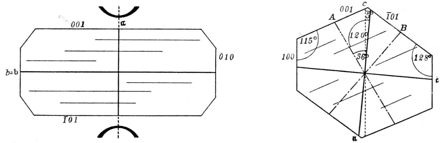
Epidote.
Fig. 61. Fig. 62.
Ortho pinacoid section. Clino pinacoid section.
95Twinning.—May occur but rarely noticed. Irregular interpenetrations
common with other members of the group; also parallel
growths.
Color.—Colorless to yellowish (Fe poor) or yellow to greenish
to yellow-brown (Fe rich).
Index of Refraction.—n′ = 1.751 but may be lower (α = 1.731,
γ = 1.768), hence relief high and surface rough.
Cleavage.—Parallel to base (001), Figs. 61 and 62, imperfect
parallel to ortho pinacoid (100). Basal cleavage cracks not very
numerous and appear parallel to general direction of elongation.
Polarized light:
Pleochroism.—Varies with the color, being faint in the light colored
varieties, but strong when the color is marked (Fe rich).
Crossed Nicols:
Double Refraction.—Variable, often very strong (γ − α = 0.037).
Interference Colors.—Variable, often high (third) orders. Intergrowths
with other members of the group are clearly shown by the
“flecked” interference colors.
Extinction.—Parallel to cleavage in sections parallel to [=b] axis.
In other sections extinction angles vary, see Fig. 62.
Convergent Light: Axial plane ∥ (010), i. e., at right angles
to the elongation of crystal and cleavage cracks, Fig. 61. Bxa.-(a)
Λ ć= 3° behind. Basal cleavage flakes show the almost ⟂
emergence of an optic axis. Axial angles very large (2E > 180°).
Optical character (−).
Alteration: Does not take place readily.
Distinguished from: Light colored Monoclinic Pyroxene.—By
having plane of optic axes at right angles to cleavage cracks
and direction of elongation; while in pyroxene plane of optic axes
is parallel to parallel prismatic cleavage cracks or bisects the angle
between intersecting cracks. Furthermore the yellow color is rare
in pyroxene.
Remarks: Epidote is essentially a secondary mineral, resulting from the alteration
of the feldspars and the ferro-magnesium silicates. It is found in crystalline
schists (especially those containing hornblende), gneiss, gabbro, diorite, diabase,
lime-silicate hornstones, contact rocks, etc. Epidote is partially decomposed by
hydrochloric acid. The Fe rich epidote can be changed to an intense color by
“glowing” in the air. H., 6 to 7. Sp. gr., 3.32 to 3.45.
Piedmontite (containing Mn).—Red in color. Very pleochroic,
red to yellow. Found in crystalline schists, the porphyrite of
96Scotland, the famous “Porfido rosso antico” of Egypt and in
certain Japanese mica schists.
ZOISITE.
Essentially orthorhombic? members of Epidote group.
[95]
Composition: Like epidote but without any Fe.
Usual Appearance in Sections: Similar to epidote or in columnar aggregates.
Often intergrown with epidote.
Distinguished from epidote by general absence of color (colorless to yellowish)
and pleochroism; by slightly lower refractive index (n′ = 1.699 to 1.720) and by
much weaker double refraction (γ − α = 0.005 and less). The interference colors
are very low order, gray to white, but anomalous colors are often seen (yellow or
prussian blue). Extinction is in general parallel to pinacoidal cleavage cracks
(except in clinozoisite).
The plane of the optic axes may be parallel or at right angles to cleavage cracks,
and the optical character is (+).
Remarks: Generally a secondary mineral. Found in crystalline schists, amphibolites,
contact rocks, eclogite, etc., and in “saussurite.” May be hard to
distinguish from vesuvianite and apatite.
ALLANITE, Orthite.
Monoclinic member of Epidote group.
Composition: Like epidote but containing cerium.
Usual Appearance in Sections: Similar to epidote in form; but distinguished
by brown color (may be also almost colorless), strong pleochroism and absorption,
and medium to weak double refraction (γ − α = 0.002 to 0.030). Lamellar twinning
clearly seen on account of oblique extinction. When included in hornblende and
mica it is surrounded by pleochroic halos. n′ = 1.78 about. Optical character (±).
Usually perfectly fresh.
Remarks: Found as an accessory mineral in SiO2 rich eruptive rocks and connected
crystalline schists, and (light colored) in amphibolite and eclogite.
TITANITE, Sphene.
| Anisotropic. |
Biaxial. |
Monoclinic. |
| Composition: CaTiSiO5. |
|
Elongation ∥ a′.[96] |
Usual Appearance in Sections: Wedge-shaped crystals (in Na
rich rocks, more prismatically developed); grains, which may be
elongated; and aggregates of small rounded particles, which appear
nearly opaque. Sections of crystals commonly acute rhombs, Fig.
63.
97Twinning.—Occurs, the twinning boundary bisecting the acute
angles of the rhomb (only noticed between crossed nicols), Fig. 64.
Color.—Reddish-brown to yellowish to colorless.
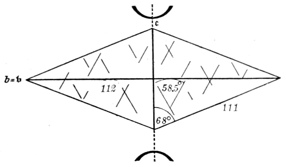
Fig. 63.—Titanite, showing acute rhombic cross-section.
Index of Refraction.—n′
= 1.920 to 1.963 (α
= 1.888 to 1.913, γ =
1.978 to 2.054), hence relief
very marked and surface
very rough.
Cleavage.—Imperfect
and not parallel to predominant
form, hence
only appears as a few
rough cracks, which are
not parallel to any crystallographic boundary, Fig. 63. Cleavage
rarely observed in secondary grains.
Polarized Light:
Pleochroism.—Varies with the color, being more distinct in colored
crystals, yellowish (the lighter color) ∥ a′ and reddish-brown
∥ c′. Scarcely noticed when the color is light.
Crossed Nicols:
Double Refraction.—Very strong (γ − α = 0.090 to 0.141).
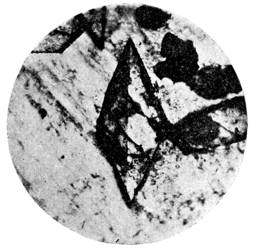
Fig. 64.—Titanite, showing twinning in nepheline-syenite. (From Cohen.)
Interference Colors.—Very high order, like those of calcite. Due
to the fact that the refractive indices of two of the rays are very
nearly alike, some sections may show very low order colors.
98Extinction.—Extinction angles not characteristic. There may
be no complete extinction in white light, owing to dispersion.
Convergent Light: On account of the very strong characteristic
dispersion of the optic axes (ρ > ν), the axial angle varies a
good deal with the color of the light used, (St. Gotthard) 2EIA = 57°,
2ETl = 47°. By using colored glasses this variation in the axial
angle can be seen. The axial plane lies in the clino pinacoid (010),
hence bisects the obtuse angle in the rhombic cross-section, Fig. 63.
Bxa.(c) Λ ć = 51° front. The optical character is (+).
Alteration: May take place.
Distinguished from:
(a) Staurolite.—In convergent light the axial plane is shown
to be in the shorter diagonal of the rhombic cross-section, while in
staurolite it is in the longer diagonal.
(b) Rutile.—By biaxial character.
(c) Calcite.—The light colored titanite (sphene), in absence
of twinning, by higher index of refraction.
Titanite may easily be confused with some of the rarer minerals.
Remarks: Titanite is always an accessory mineral and is found distributed in
all rocks, except SiO2 rich eruptive and magnesia silicate rocks. As a secondary
mineral it forms rims around other titanium minerals or pseudomorphs after them
and also the principal part of leucoxene. It is partly soluble in hot hydrochloric
acid and completely decomposed by sulphuric acid. H., 5 to 5.5. Sp. gr., 3.3 to
3.7. In a specific gravity separation it falls with the ferruginous minerals (on
account of its density) and from these can generally be separated by electromagnetic
methods.
FELDSPAR GROUP.
Orthoclase, Microcline and the Plagioclases.
ORTHOCLASE.
| Anisotropic. |
Biaxial. |
Monoclinic. |
| |
Elongation (∥ cleavage) ∥ a′. |
|
Composition: KAlSi3O8, with some replacement by Na.
Usual Appearance in Sections: In crystals and grains. In porphyritic
rocks habit of crystals more or less tabular parallel to
clino pinacoid (010), or rectangular much extended parallel to
clino axis à, with cross-sections six-sided, or rectangular to long
lath shape, Figs. 65 and 66. Crystals may be changed into rounded
or looped grains by chemical corrosion, Fig. 6. Adularia crystals
99more prismatically developed, giving rhombic sections. Dimensions
of crystals vary extremely; microlites occur, at times forming
sphærulitic structure. The very fine grained ground-mass “microfelsite”
(not resolved by the microscope) consists largely of
feldspar.
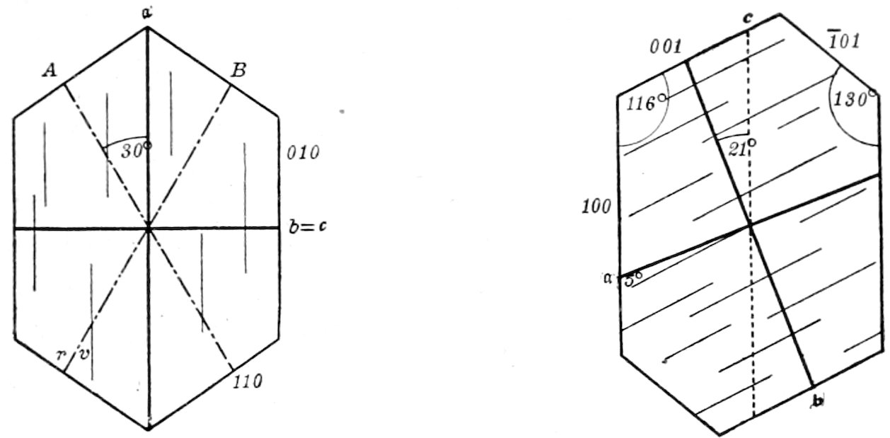
Orthoclase cleavage plates.
Fig. 65.—Basal. Fig. 66.—Clino pinacoid.
Intergrowths with microcline and plagioclase common, forming
“microperthite” when lamellæ are microscopic. May be in zonal
formation with plagioclase (the orthoclase on the periphery).
Also intergrown with quartz[97] forming “pegmatite” and “micro-pegmatite,”
Fig. 67.
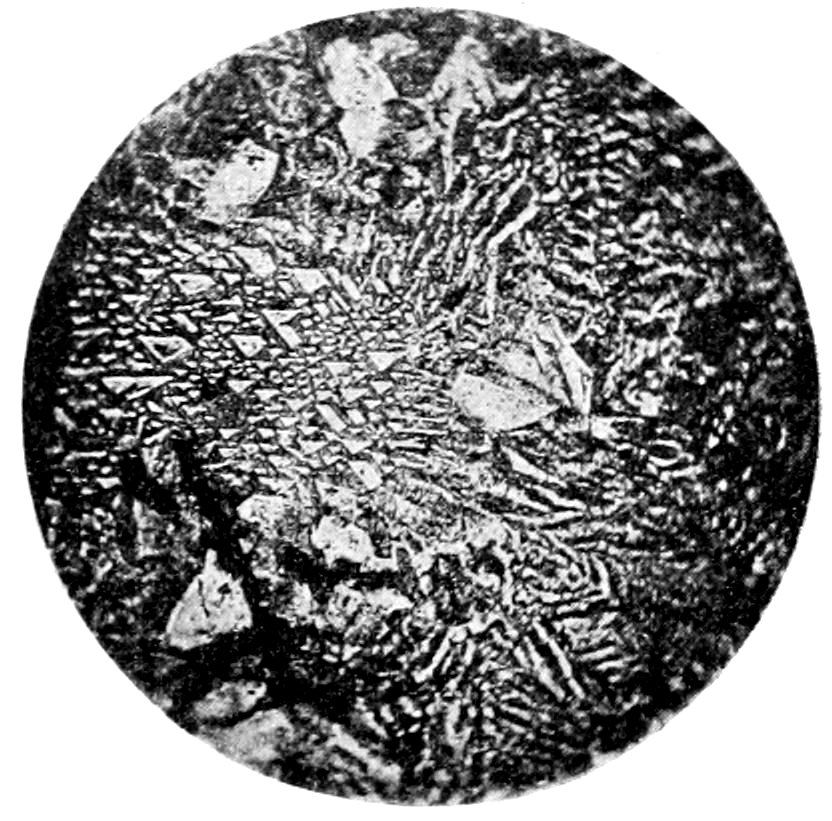
Fig. 67.—Micro-pegmatitic structure, in granophyric quartz-porphyry. (From Cohen.)
100Zonal structure often seen, Fig. 20, especially when decomposition
has commenced; and in fresh crystals may be indicated by
zonal arrangement of inclusions.
Twinning.—Very common, generally after Carlsbad law, Figs. 18
and 69; the twinning boundary, dividing the section longitudinally,
either being parallel to edges of crystal or bent or jagged. Twinning
after Baveno (twinning boundary diagonal, with the two parts
extinguishing at the same time, but having a and c directions
crossed in the two portions) and Manebach laws less common.[98]
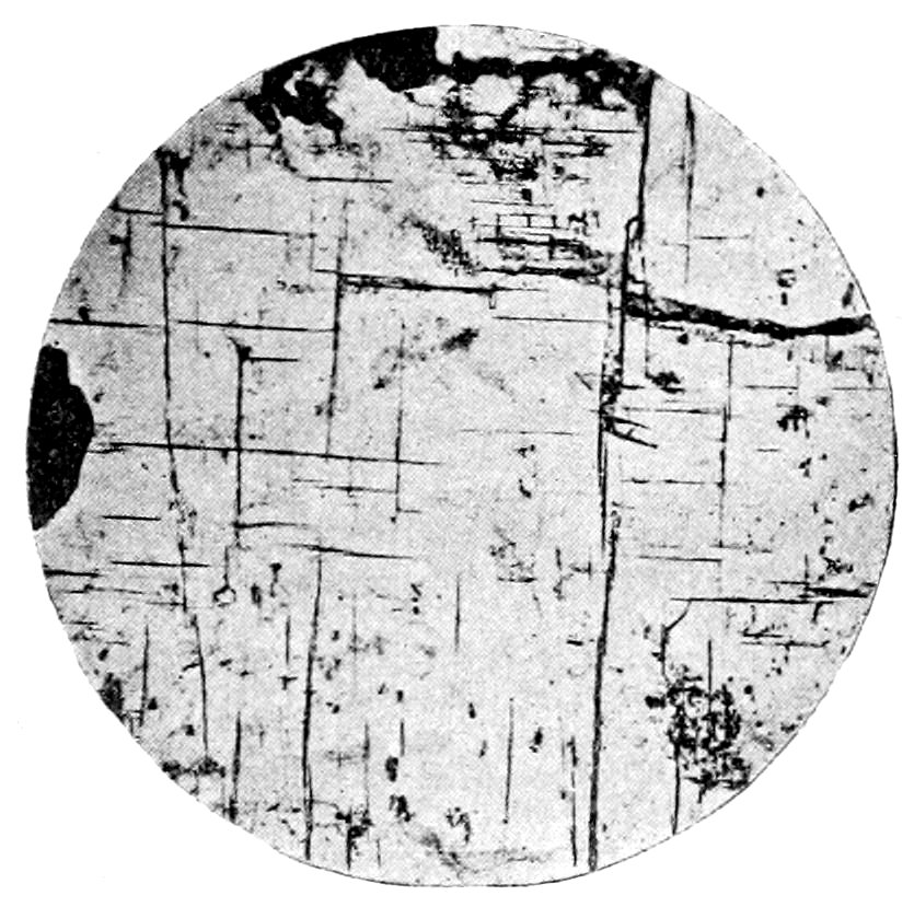
Fig. 68.—Orthoclase, ortho pinacoid section showing cleavages intersecting at 90°, in augite-syenite.
Color.—Colorless or tinged by oxide of iron. Cloudy if decomposed.
Index of Refraction.—n′ = 1.523 (α = 1.519, γ = 1.526), hence no
relief and surface smooth.
Cleavage.—Varies and sometimes only seen in very thin sections,
but is an important character and should always be searched
for. It occurs perfect, parallel to base (001), and almost as perfect
parallel to clino pinacoid (010). The two cleavages intersect
at 90° in section parallel to the [=b] axis, Fig. 68.
Inclusions.—May be present and arranged in regular or zonal
order, but not important. Do not occur in individuals of a second
generation.
Polarized Light:
Pleochroism.—None.
101Crossed Nicols:
Double Refraction.—Very weak (γ − α = 0.007).
Interference Colors.—Lower first order, gray, white, etc., not
quite so bright as colors of quartz and plagioclase.
Extinction.—Being monoclinic the extinction angle on base
(001), with reference to clino pinacoid (010) cleavage cracks, is
0°. On clino pinacoid with reference to basal cleavage cracks, it
is 5°. Some sections (notably in glassy sanidine grains) may
appear dark during complete rotation. This is due to the fact that
the axial angle is very small and the sections act approximately
like those of a uniaxial mineral at right angles to the optic axis.
Convergent Light:[99] Plane of optic axes in general at right
angles to clino pinacoid (010) (plane of symmetry), Fig. 65, hence
parallel to trace of basal cleavage; but in some sanidines parallel
to plane of symmetry. Bxa (a) Λ a = 5° above. Axial angles
vary, 2E = 125° (orthoclase), 0°–50° (sanidine).[100] May appear
uniaxial when axial angle is very small. Optical character (−).
Alteration: Very common to clay,[101] muscovite, hydrargillite,
etc. Generally commences along the cleavage cracks, and when
it has progressed very far the whole feldspar appears opaque or
cloudy, and no perceptible change may take place between crossed
nicols. As decomposition is very prevalent in many rocks, the
orthoclase is rarely clear or pellucid. Epidote is often formed when
accessory solutions are present.
Distinguished from:
(a) The other Feldspars and Melilite.—See under the latter
minerals.
(b) Quartz.—Feldspar is biaxial but when occurring in clear
glassy grains (notably sanidine), which appear uniaxial in convergent
102light, may resemble quartz. When tested the optical character
is (−), while that of quartz is (+).
Remarks: The members of the feldspar group are the widest distributed of
the rock-forming minerals and their recognition is of the utmost importance on
account of their bearing on the systematic classification of rocks. Orthoclase is
found as an essential constituent in the more acid plutonic and older volcanic
rocks, as granite, syenite, trachyte, porphyry, and also in gneiss, crystalline schists,
more seldom in contact rocks and subordinate in clastic rocks.
Chemical corrosion (producing rounded or looped grains), Fig. 6, and mechanical
deformation (producing angular, sharp-edged, broken grains, bending and
undulatory extinction[102]), Fig. 7, occur in orthoclase. When a rock containing
feldspar crystals is shattered, the orthoclase breaks parallel to basal cleavage and
plagioclase parallel to twinning plane. Orthoclase is practically insoluble in acids.
H., 6 to 6.5. Sp. gr., 2.56.
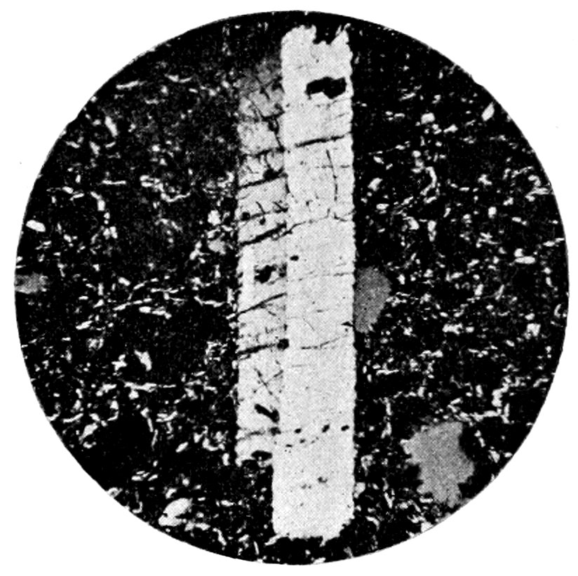
Fig. 69. —Sanidine, showing Carlsbad twin and cross-parting, in nepheline-phonolite. (From Cohen.)
Sanidine.—This clear, glassy variety of orthoclase occurs in the
later eruptive rocks, rhyolite, trachyte, obsidian, etc. Sanidine
often has a parting parallel to ortho pinacoid (100), which may be
noticed in sections so thick that the cleavage is not seen, Fig. 69.
In general it shows no sign of decomposition, and has a smaller
axial angle than orthoclase. Inclusions of glass are more abundant
than in orthoclase.
MICROCLINE.
| Anisotropic. |
Biaxial. |
Triclinic. |
| Composition: KAlSi3O8. |
|
|
Usual Appearance in Sections: As a rock constituent in irregular
grains.
103In general characters like orthoclase and distinguished from it
and the plagioclases by characteristic “gridiron” structure between
crossed nicols, resulting from the polysynthetic twinning after both
Albite and Pericline laws, Fig. 19. This crossed twinning will
show in all sections except those parallel to the brachy pinacoid
(010). The lamellæ are generally thinner than in the plagioclases
and more “spindle-shaped.”[103]
Furthermore the rather obscure triclinic crystallization is shown
by an extinction angle of + 15° on basal cleavage plates with reference
to brachy pinacoid (010) cleavage lines (distinction from
orthoclase, which has O° extinction angle).
Remarks: Found with orthoclase, often almost replacing it, in granite, syenite,
gneiss, etc., and is one of the last minerals to form. It is notably resistant to
decomposition. A structure like the microcline twin structure may be produced
in orthoclase by dynamic action.[104]
THE PLAGIOCLASES.
Albite, Oligoclase, Labradorite, Anorthite.
| Anisotropic. |
Biaxial. |
Triclinic. |
Elongation (∥ Albite twin lamellæ) ∥ a′ (except in anorthite
when it may be ∥ a′ or c′).
Composition:[105]
Albite, NaAlSi3O8.
Oligoclase, n(NaAlSi3O8) + CaAl2Si2O8, or n Ab + An, n = 2
to 6.
Labradorite, NaAlSi3O8 + n(CaAl2Si2O8), or Ab + n An, n = 1,
2 or 3.
Anorthite, CaAl2Si2O8.
Usual Appearance in Sections: Much the same as orthoclase.
Lath-shaped[106] forms and microlites very common, especially in
the acid series.
104
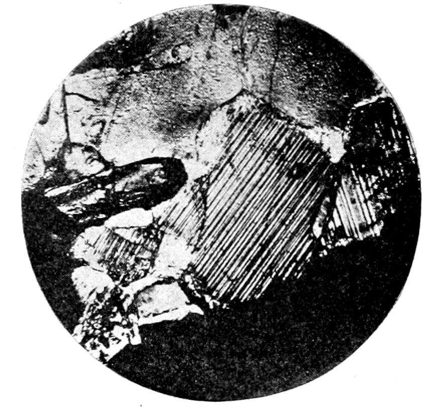
Fig. 70.—Plagioclase, showing narrow lamellæ, in diabase. (From Cohen.)
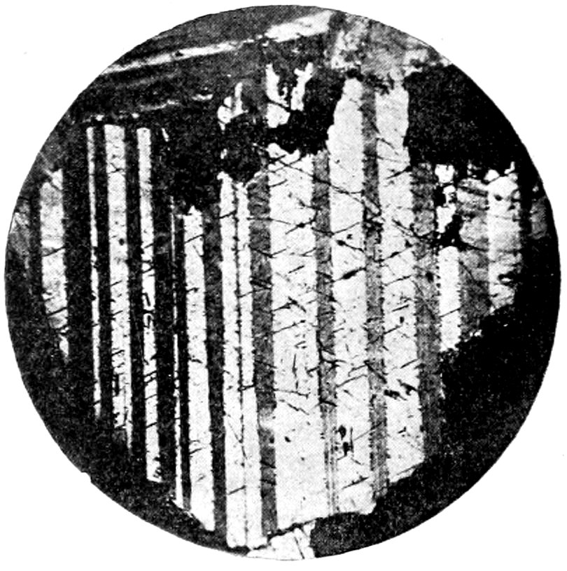
Fig. 71.—Plagioclase, showing broad lamellæ, in gabbro. (From Cohen.)
Twinning.—Polysynthetic, after Albite law, almost universal;
the twinning appearing between crossed nicols as a series of dark
and light bands, bounded by parallel edges, Figs. 70 and 71. The
twin lamellæ are parallel to brachy pinacoid (010), hence not
observed in sections parallel to this pinacoid. The lamellæ may
appear irregular and interrupted, and seem to be broader in
the basic than in the acid series. When this twinning fails, however,
as in the basic plagioclases in certain metamorphic rocks,
the determination becomes very difficult. In some cases polysynthetic
twinning, after both Albite and Pericline laws, may
take place at the same time, giving rise to a structure somewhat
similar to that of microcline, Fig. 72. In addition the polysynthetic
105crystals may be twinned like orthoclase after Carlsbad
and Baveno laws.
The general characters are the same as in orthoclase with the following differences:
| Indices of Refraction: |
n′ = 1.535 (α = 1.532, γ = 1.540) Albite. |
| |
n′ = 1.541 (α = 1.537, γ = 1.545) Oligoclase, Ab4An1. |
| |
n′ = 1.559 (α = 1.555. γ = 1.563) Labradorite, Ab1An1. |
| |
n′ = 1.582 (α = 1.575, γ = 1.588) Anorthite. |
The surface of anorthite appears slightly rougher than that of
orthoclase.
Cleavages, parallel to base (001) and brachy pinacoid (010),
never intersect at right angles, as is the case in sections of orthoclase
parallel to [=b] axis. This is due to the triclinic system of
crystallization, but the divergence from a right angle is small (93°
36′ to 94° 10′).
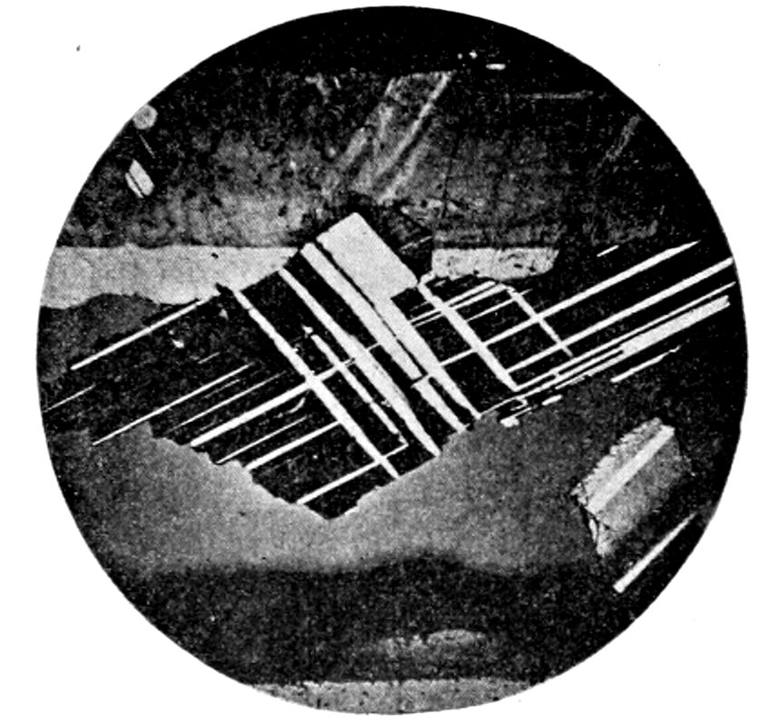
Fig. 72.—Plagioclase, showing crossed lamellæ, in olivine-gabbro. (From Cohen.)
Inclusions at times may be quite important, as the vitreous inclusions
of oligoclase in andesites, etc., and the iron ore inclusions
and other microlites in labradorite. The arrangement of these
inclusions may be zonal or in parallel orientation.
Double refraction is a little stronger than for orthoclase (γ − α
= 0.008 to 0.013 (anorthite)), hence producing slightly brighter
interference colors in sections of the same thickness.
106Extinction takes place in all sections unsymmetrically with respect
to crystallographic, twinning or cleavage lines (as these
minerals are triclinic); hence extinction angles are always observed.
Convergent Light: All plagioclases show the emergence of a
bisectrix,[107] more or less oblique, on brachy pinacoid (010) cleavage
faces. These cleavage faces show no twin lamellæ, unless twinning
after Pericline law occurs, in which case the determination is much
more complicated. The axial angle is large, 2E = 155° (Albite).
Optical character, depending on variety, (+) or (−).
Alteration: Partly the same as in orthoclase, forming clay,
muscovite, etc. Calcite and epidote are more common as side-products,
and zeolitization also occurs in some rocks. The plagioclases
decompose more easily than orthoclase.
Distinguished from:
(a) Orthoclase.—By repeated twinning after Albite law, giving
between crossed nicols a series of alternate dark and light bands.
When Albite twinning is absent the distinction is very difficult.
(b) Microcline.—By common absence of the microcline “gridiron”
structure between crossed nicols.
Methods for Optical Determination of the Plagioclases.[108]
The correct determination of the particular plagioclase is of the
greatest importance in the classification of rocks, and it is no longer
sufficient to simply determine the feldspar as either orthoclase or
plagioclase.
A quantitative analysis of isolated material would lead most
surely to the desired result, but has many objections.
Modern optical methods now permit of a very accurate and convenient
determination under ordinary circumstances. But of
course these methods involve a knowledge of the approximate
orientation of the section tested. When this section is not a definite
cleavage fragment, its orientation can best be determined by
convergent light tests.
Only an outline of these methods can be here given, and reference
107should be made to more complete works for an elaborate
discussion of the subject.
It is very convenient to have at hand a set of glass models of
the plagioclases, showing location of plane of optic axes, vibration
directions and crystal axes.[109]
(1) Schuster’s method of recognizing the different feldspars by
extinction angles measured on the cleavage plates[110] is very precise,
but not always applicable for crystals in rock sections.
Extinction Angles:
| Extinction Angles: |
|---|
| ON BASE, MEASURED FROM TRACE OF PINACOIDAL CLEAVAGE. |
ON BRACHY PINACOID, MEASURED FROM TRACE OF BASAL CLEAVAGE. |
| Albite |
+ 4° |
Albite |
+19½° |
| Oligoclase, Ab4An1 |
+ 2° |
Oligoclase, Ab4An1 |
+ 8° |
| Labradorite, Ab1An1 |
− 5½° |
Labradorite, Ab1An1 |
−20° |
| Anorthite |
−36½° |
Anorthite |
−41½° |
Confusion may here arise between albite and labradorite if disregard
be had to signs, but the more acid oligoclase is readily
distinguished from the basic anorthite.
By convention the angles on base and pinacoids are (+) when
the direction of extinction has apparently moved as the hands of a
watch, with reference to the upper right hand edge (between base
and pinacoid) of the crystal. When the reverse is true the angles
are (−), see Fig. 73.
(2) The statistical method of Michel Lévy and others is often
applicable, especially in the following case:
Sections at right angles to the brachy pinacoid (010) and hence
showing Albite twinning.—These sections, as nearly perpendicular
108to the lamellæ as possible, are known by
the sharp dividing lines, by the extinction
angles on each side of the trace of the twinning
plane being approximately equal and
by the fact that the two adjacent lamellæ
are of the same color when the trace of
the twinning plane is parallel to the plane
of vibration of either nicol. Also in
the 45° position the lamellæ are exactly
the same color and the dividing lines disappear.
Measure the extinction angles in
as many sections thus selected as possible
and take the maximum value.[111] This should
be very close to the maximum extinction
angle, which is a constant for each kind of
feldspar.
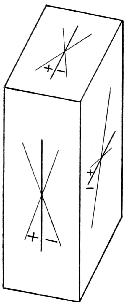
Fig. 73.—Showing conventional signs of extinction angles.
| Maximum Extinction Angles in Sections Perpendicular to Albite Twins. |
|---|
| Albite |
16° |
| Oligoclase, Ab4An1 |
5° |
| Labradorite, Ab1An1 |
27° |
| Anorthite |
53° |
In the determination of rod-like microlites,[112] oligoclase extinguishes
almost parallel to its length, while anorthite may show
extinction angles of over 27°. When these microlites show Albite
twinning use the method just described.
(3) Fouqué’s method[113] can be used when the optical orientation
109of the section is known (as the result of a test with convergent
light). The extinction angles of these known sections are of great
diagnostic importance.
The best sections are those at right angles to the two bisectrices,
and these may be obtained by rapidly testing those sections,
in the rock, which show an interference color about half as high as
the maximum color in the rock section, in this way avoiding the
sections parallel to the optic axes.
Having found such a section, test it with a gypsum or ¼ undulation
mica plate to prove whether the bisectrix is ⟂ a or c. If
⟂ a (these sections show sharp twinning striations) measure extinction
angle between trace of axial plane and albite twinning; if
⟂ c measure extinction angle between trace of axial plane and
basal cleavage cracks.
| Extinction Angles in Sections:[114] |
|---|
| ⟂ a, Measured from Albite striations. |
⟂ c, Measured from cleavage cracks. |
| Albite |
74° |
19½° |
| Oligoclase, Ab4An1 |
88° |
5° |
| Labradorite, Ab1An1 |
60° |
22° |
| Anorthite |
55½° |
48° |
When both extinction angles can be obtained, the determination
of the plagioclase is very certain, but the result cannot be regarded
as definite when only one is found; and the method becomes
more difficult as the crystals become smaller.
The position of the axial plane should be determined by convergent
light test and not simply by the direction of extinction in
parallel polarized light.
(4) Michel Lévy’s method[115] can be employed when twinning is
present after both Carlsbad and Albite laws.
110
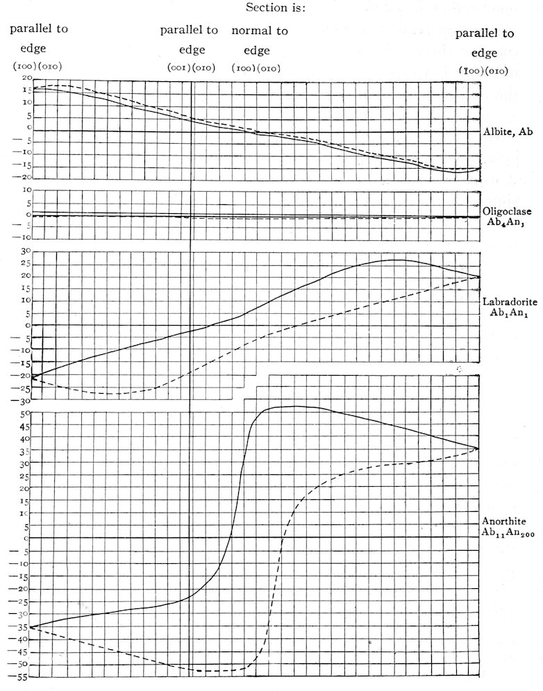
Fig. 74.—Extinction Angles in the Zone normal to (010) in Carlsbad Twins of the Plagioclases.
111The section to be tested should be in the zone perpendicular to
(010). Such sections show sharp boundary lines between the
twin lamellæ and, between crossed nicols, the Albite lamellæ show
the same interference color when the trace of (010) is parallel to
the cross-wires of the ocular, and also in the 45° position the
lamellæ are the same color and no dividing lines show. The two
parts of the Carlsbad twin exhibit different interference colors in
the 45° position, this difference being more marked as the composition
approaches that of Anorthite. The extinction angles are
measured from the trace of the Albite twinning plane (010), paying
regard to the + and − signs, and the concurrent series of angles
are to be obtained from the two parts of the Carlsbad twin. The
range of these angles (for four type compositions, Ab, Ab4An1,
Ab1An1 and An) is given in the accompanying diagram for all
positions of the section in the zone normal to (010).
In the curves of this diagram (Fig. 74) the vertical distances
are the extinction angles for every ten degrees measured from the
trace of the Albite twinning plane, and the horizontal distances
represent varying positions of the section in the zone normal to
(010) for every ten degrees of rotation from the position ∥ to the
edge (100)(010) (that is ∥ ć axis), through a revolution of 180°
to again ∥ to the same position. The concurrent angles in one
part of a Carlsbad twin are represented by a heavy line and in the
other part by a broken line. It will be observed that the difference
between these concurrent angles is very small in Albite (3°) and
increases markedly towards Anorthite (60°).
| Table for Becke Method.[116] |
|---|
| Orthoclase |
α |
< ω Quartz |
| Microcline |
β |
| Albite |
γ |
| Oligoclase, Ab4An1 |
α |
< ω; γ > ω Quartz. |
| Labradorite, Ab1An1 |
α |
>ε Quartz |
| Anorthite |
β |
| γ |
112(5) Becke’s method may be employed to identify the feldspar,
by determining the relative values of the indices of refraction of the
feldspar grain when it lies in contact with a quartz grain (best results)
or with the balsam (not such good results.) The grains
should have vibration directions in parallel position.
Other methods that may be employed are here simply referred
to: Determination (in convergent light) of the emergence of an
optic axis with reference to a known plane, the basic plagioclases
show an optic axis about parallel to ć of the crystal; determination
of total reflection by Wallerant’s total reflectometer; determination
of the value of the mean index of refraction of crushed
isolated grains by Schrœder van der Kolk’s method;[117] determinations
by specific gravity separations with use of heavy solutions, and
by chemical and micro-chemical tests (for the relative amounts of
K, Na and Ca).[118]
Remarks: The plagioclases may have the same two general habits as orthoclase,
being glassy and colorless in the younger eruptive rocks, and dull and
cloudy in the granular and porphyritic, older, massive and schistose rocks.
They occur in rocks of intermediate and basic composition.
Albite is found in granite (commonly intergrown with orthoclase), gneiss, etc.,
and frequently as a secondary constituent (secondary feldspar[119]) in the feldspar-quartz
mosaic of mechanically metamorphosed rocks. It may also be present in
acid eruptive rocks.
Oligoclase is very frequent in granite, syenite, gneiss, diorite, trachyte, andesite,
diabase, etc.; and particularly accompanies orthoclase.
Labradorite is confined more to the gabbros,[120] basic eruptive rocks and crystalline
schists, rich in amphibole and pyroxene.
Anorthite occurs in gabbros, the most basic porphyrites, basalts, etc.
Chemical corrosion and mechanical deformation[121] may take place as in
orthoclase.
Anorthite and labradorite are more or less decomposed by hydrochloric acid,
while albite and oligoclase are not acted on by the acid.
Especially interesting is the alteration of the plagioclase that takes place in
113gabbros, accompanied by “uralitization” of the pyroxene, forming “saussurite.”
This consists of a white to greenish confused aggregate, chiefly of zoisite, grossularite,
vesuvianite, chlorite, secondary feldspar (albite), etc.
Anorthoclase (a Na K, triclinic, feldspar).—Shows between
crossed nicols intersecting areas of exceedingly fine composite
twin structure and others of homogeneous structure, producing a
watery or “moiré” appearance. The twin structure may be only
seen in very thin sections. All possible kinds of perthitic intergrowth
occur. Further distinguished from orthoclase by small
extinction angle (4°) on base and by smaller axial angle (2E
= 72° to 88°).
Replaces orthoclase in the Na rich eruptives. Found in augite-syenite and
“Rhombenporphyr” of Norway (with rhombic cross-section), acid augite-andesite
of Pantelleria and in the porphyries of the Hartz.
CYANITE, Disthene.
| Anisotropic. |
Biaxial. |
Triclinic. |
| Composition: Al2SiO5. |
|
Elongation ∥ c′. |
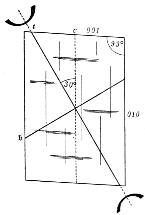
Fig. 75.—Cyanite, macro pinacoid cleavage section.
Usual Appearance in Sections: Blade-like crystals without terminal planes,
but with cross-section (six-sided) showing two long parallel edges and four
shorter edges; also in columnar aggregates. Twinning common, with generally
twinning plane parallel to macro pinacoid (100). Colorless or bluish and spotted.
The index of refraction is high (n′ = 1.720, α =
1.712, γ = 1.728), hence relief marked and surface
rough. Cleavage perfect, parallel to macro pinacoid
(100), appearing as sharp cracks, parallel to longest
edges in cross-sections; less distinct, parallel to
brachy pinacoid (010). Fibrous parting parallel to
base (001), Fig. 75. Pleochroism (colorless to blue
∥ c′) not noticed except in colored crystals.
Crossed Nicols: Double refraction quite strong
(γ − α = 0.016). Interference colors upper first
order, yellow, red, violet, etc. Extinction angles
observed in all sections (being triclinic), reaching
a maximum of 30° on macro pinacoid (100), Fig.
75. Extinction on base, about parallel to most
perfect cleavage. In convergent light axial angle
large; axial plane and Bxa. about perpendicular
to best cleavage (100); optical character (−).
Alteration: Seldom observed, but may take
place to mica.
Distinguished from:
(a) Amphibole by cleavage (intersecting cleavages at 124° in amphibole and
90° in cyanite) and by (100) cleavage plates of cyanite showing emergence of
acute bisectrix.
(b) Corundum by being biaxial.
114Distinction from similar appearing minerals may be difficult.
Remarks: Found in gneiss, granulite, metamorphic schists, ecolgite, etc., commonly
associated with garnet. It is not attacked by acids. H., 5 to 7. Sp. gr.,
3.6.
SERPENTINE.
| |
Aggregate. |
|
| Elongation (of fibers) ∥ c′. |
Composition: H4Mg3Si2O9, with replacement by Fe.
Usual Appearance in Sections: Dense, fibrous (chrysotile) or
scaly (antigorite) aggregates.
Color.—Colorless to light greenish, except the Fe rich variety
which is green.
Index of Refraction.—n′ = 1.55 to 1.56 (α = 1.56, γ = 1.571 for
antigorite), hence no relief and surface smooth.
Polarized Light:
Pleochroism.—Not seen or very feeble, except in the Fe rich
variety.
Crossed Nicols:
Double Refraction.—Rather weak (γ − α = 0.009 to 0.011).
Interference Colors.—Middle first order, gray, white, yellow,
etc. Anomalous colors do not appear. The aggregate structure
is distinctly seen between crossed nicols. Due to compensation
aggregates may appear isotropic.
Distinguished from: Chlorite.—By more usual absence of
color, pleochroism and anomalous interference colors; but this
distinction may be very difficult.
Remarks: Serpentine (both antigorite and chrysotile) is essentially a secondary
mineral, resulting in most cases from the alteration of chrysolite (olivine), Fig.
22, more rarely of pyroxene or amphibole.[122] The alteration of olivine to antigorite
leads to the characteristic “lattice structure,” the alteration to chrysotile to “mesh
structure.” In the case of the “mesh” formation the alteration starts from the
surface and cracks, producing fibres of chrysotile, which stand at right angles to
these edges and cracks. As serpentinization proceeds new cracks form, due to
increase in volume, and the process may continue until complete pseudomorphism
takes place. When this subsequent serpentinization of the meshes takes place
the resulting serpentine may appear almost isotropic[123] and is certainly different
from the chrysotile of the first formed veins (Weinschenk). Pieces of the parent
mineral are often present.
115Serpentine is found in ophiolites, the altered basic igneous rocks, pyroxenites,
peridotites, etc., and as a primary mineral in the Central Alps peridotite, intergrown
with fresh olivine (Weinschenk). It may also form a rock by itself. Serpentine
is attacked quite strongly by hydrochloric acid, still more so by sulphuric
acid. Common serpentine is not altered by heating (distinction from chlorite),
but the Fe rich variety becomes brown and opaque. H., 2.5 to 4. Sp. gr., 2.5 to 2.7.
CLAY, Kaolin.
| Composition: H4Al2Si2O9 (kaolinite). |
|
Aggregate. |
Usual Appearance in Sections: Fine, scaly, colorless aggregates, which appear
opaque (due to porous structure). The scales show basal cleavage. Index
of refraction is about the same as balsam (n′ = 1.55), hence no relief. The
double refraction is weak (γ − α = 0.008).
Distinguished from: Colorless Mica and Hydrargillite [(Al(OH)3), which
as an alteration product of the feldspars is often confused with clay] by weak
double refraction.
Remarks: Clay results from the alteration of the feldspars (especially the
plagioclases), elæolite, scapolite and other silicates. Kaolinite is insoluble in
hydrochloric but decomposed by sulphuric acid. H., 2.5. Sp. gr., 2.6.
117
CHAPTER V.
Methods of Preparing Sections.[124]
The methods described will be those used in making rock sections.
The general principles involved are the same for both rock
and crystal sections; although more difficulties are encountered
in making the latter, due to the sections being required in some
definite direction or of some precise thickness, or on account of
the possibly fragile or brittle character of the crystals.
In the case of rock sections any section, taken “at will”
through the rock, will generally do.
Cutting and Grinding Machines.[125]
Many different kinds are used, the power being furnished by
steam, electric motor[126] or by the hand or foot.
The chip or fragment of rock to be sliced should be comparatively
small in size, and may be cut by either a vertical diamond saw
or by a horizontal emery-disc. The fragment is held
in position by suitable guides. The moistened emery can be kept
in the tray and fed to the disc by a spoon or some other device.
Diamond saws are only needed in the case of hard rocks.
For cutting sections of crystals in definite directions a form of
small hand apparatus[127] is shown in Fig. 76.
This cut shows how the plate, to which the crystal is cemented,
can be given definite rotation in two directions. The simpler
crystal holder, appearing loose on the stand, may be used when a
section is required parallel to the face of the crystal cemented to
the holder.
118In these machines the cutting is done with rotating saws of
sheet-tin, usually charged with either diamond dust or emery.
In the case of a very small crystal a section, parallel to any desired
face, can be obtained by cementing this face to a suitable
frame or holder and grinding down by hand on a glass plate with
emery, the final polish being given with rouge. When the section
required is not parallel to a crystallographic face or cleavage
it must be verified geometrically with reference to other faces. If
the crystals are soluble in water, some other liquid, as α bromnaphthalin
or benzine, must be used in grinding; and very fragile
crystals are rubbed down on a ground glass plate without emery
or rouge, simply using bromnaphthalin or some other appropriate
liquid.
When sections of a crystal are desired with strictly parallel faces,
the form of grinding apparatus shown in Fig. 77 can be used.
This apparatus consists of a cylinder, held within a suitable
119frame supported on three set-screws, a1, a2 and a3, of hard steel.
The lower surface of the frame and consequently the bottom of the
cylinder can be adjusted by the wedge k and the set-screws so that
it is exactly parallel to the grinding surface of the glass plate.
The crystal to be ground down, p, is cemented to the bottom of
the cylinder, and the whole apparatus rubbed over the grinding
surface of the plate. The pressure of the hand on the upper part
of the cylinder regulates the pressure of the crystal on the grinding
surface. In this way a surface is obtained which is exactly
parallel to the surface cemented to the cylinder.
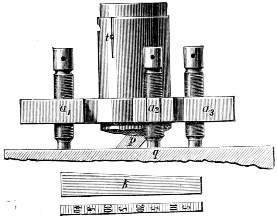
Sections of definite thickness can also be obtained by using this
apparatus; for the adjustments with the wedge k may be so arranged
that, when the stop t in the cylinder has reached the bottom
of the slot in the frame, the lower surface of the cylinder will
be the required distance from the grinding surface of the glass
plate. The wedge is graduated so that the value of one division
on the sloping top is known in mm. of vertical distance.
Saws.
Saws,[128] of about six inches in diameter made from ¹⁄₃₆ inch sheet-tin,
are convenient for general work, and may be charged with
diamond dust by the operator as follows:[129] Crush one or two
120carats of rough crystals of diamond-bort in a small steel mortar
to about the condition of fine sand, care being taken not to reduce
the diamond to powder. Transfer the dust to a piece of flat iron
and, after collecting it in a heap, moisten with a drop of oil. The
cutting edge of the tin disk must now be prepared by making a
series of incisions (¹⁄₁₆ inch deep) on the outer margin. This can
be done by striking the disk with a sharp, thin knife edge. The
larger the number of incisions and the closer they are together the
better. Charging the saw is accomplished by gently hammering
the edge against the iron plate, upon which is the paste of diamond
dust and oil. The disk must be slowly rotated during this
charging process, which should be continued until all portions of
the edge have been gone over two or three times.
Instead of charging with diamond dust the saws may be used
with emery. The edges of the saws should first be “upset,” as
just described, and then while rotating charged with emery. The
emery in the state of mud can be applied with the thumb and
fingers, or the saw can be allowed to pass through a tray of emery
mud. The finer grades of emery (Nos. 100 to 120) should be used.
The method of mounting saws, of course, depends on the way
the saws and spindles are constructed. It is well, however, to
have the hole in the center of the saw-disk sufficiently large to
allow of adjustment for accurate centering.
Cutting.
During the process of cutting a lubricant must be used on the
saw. Petroleum has been recommended by some, but water seems
to be the most used. Holding a piece of soap against the cutting
edge will also reduce friction. It is convenient to carry the
water to the saw through a very small lead pipe, which permits of
easy adjustment, so that the water can be delivered at just the right
spot, the flow of water, of course, being regulated by a stop-cock.
Another method for cutting sections is used by the U. S. Geological
Survey at Washington, D. C. The apparatus consists of
an endless wire of soft iron, about ³⁄₃₂ inch in diameter, revolving
over two pulleys or wheels, one of which is driven by steam-power.
The wire is charged by dipping the fingers in water,
taking up a little fine (120 grade) emery and holding the fingers
121against the wire above the section. The wire revolves so as to cut
downwards, thus carrying with it the emery taken from the fingers.
In cutting sections the thickness, of course, depends on the
character of the rock; the more porous and fragile the rock the
thicker the section should be made, an ordinary section being
about as thick as a silver quarter of a dollar.
Very often by skill and practice a suitably shaped chip or fragment
can be detached from the specimen with a hammer or with a
hammer and cleavage chisels, thus avoiding the delay and trouble
involved in the use of the section cutter.
Grinding Plates or Laps.
Copper laps, about 7–8 inches in diameter and ½ inch thick,
seem to be best for general purposes; although laps made of lead
or cast iron are also used. A lead lap, being soft, holds the emery
well and thus hastens the grinding away of the section; but at the
same time its own smooth surface is soon destroyed. A cast iron
lap is much harder and retains its smooth surface better, but does
not hold the emery so well and therefore retards the process of
grinding. Copper, being intermediate in hardness between lead
and iron, seems to combine the advantages of both.
It is always good practice to have at least two laps, one for the
preliminary grinding with coarse emery and the other for the final
grinding with the finest grades of emery. In this way one lap is
always kept with a smooth surface, making it possible to give a
uniform, plane finish to the section.
The surface of the laps should not be exactly plane, but turned
or finished so as to be a little higher (¹⁄₃₂ of an inch for diameter of
8 inches) at the axis than at the periphery; the idea being to compensate
for the more rapid abrasive action towards the periphery.
Cementing.
For grinding down to a proper thinness for transparency it is
necessary to cement the fragment of rock to a holder, which consists
of a small piece of plate-glass about ⅛ inch thick. If the
piece of rock has been cut by a good diamond saw the surface
will be comparatively smooth and uniform, and may only need
polishing (described under grinding) before cementing. When,
122however, the piece of rock is in the shape of a chip or rough fragment
it is first necessary to prepare a smooth ground surface on
one side (described under grinding) before it can be cemented to
the glass holder.
The pieces of plate-glass used should be free from flaws, bubbles
or anything tending to destroy uniformity of surface, and should
be a little larger than the chips and slices of rock for which they
are to act as holders. Hardened Canada balsam, or better yet, a
cement made of a mixture of shellac and Venice turpentine,[130]
should be used.
The process of cementing is carried on as follows: Heat the
glass support over an alcohol lamp or a Bunsen burner, place it on
a good non-conductor of heat, as a piece of wood, and rub it with
a stick of the cement until a sufficient quantity has been melted
off. The piece of rock should then be treated in the same manner,
applying the cement to the smooth finished portion. Care must
be taken that neither the glass nor rock preparation are heated too
much, as this would cause the cement to smoke or bubble. After
placing the rock preparation and plate together, use quite a little
pressure in order to drive out all superfluous cement. Examine
now, through the glass, the contact surface and see that it is entirely
free from bubbles, etc.
Bubbles are usually caused by overheating of the parts before
cementing. If only very few bubbles are seen, they may generally
be removed by moving the rock preparation rapidly back and
forth over the glass plate. If the bubbles are numerous or cannot
be removed in the manner just described, the rock preparation
must be separated from the glass plate and the cementing done
over again.
Bubbles must not be allowed to remain, as the portions of the
rock over them, not having any cement backing, are ground away
leaving holes in the section.
123
Grinding.
After the rock preparation has been cemented to its glass holder
it is ready for the grinding process, for which are used horizontal
laps, mounted on a vertical spindle in the tray T, Fig. 76. The
copper lap for the first grinding is put in place, and, after it has
commenced to rotate, is charged with emery and water. This
can conveniently be done by dropping on the emery and water,
either with the fingers or with a small bunch of rags at the end of
a stick. A large camel’s hair brush may be used for putting on
the finest emery. The emery is distributed over the rotating lap
by the motion of the rock preparation during grinding. The kind
of emery used for this first grinding depends somewhat on the
character of the rock section. If the section is composed of a hard,
compact, fine grained rock, the first emery used may be quite
coarse; the coarser the emery the more rapid being the grinding
down. For rough, quick work, Nos. 80 to 100 emery can be
used until the section becomes quite thin; then, still using the
same lap, substitute the finest corn emery (next coarsest to flour
emery) and continue grinding until the section becomes quite
translucent. The lap must then be changed, and the grinding
finished with the finest emery dust.
Too great care cannot be given to cleanliness while doing this
sort of work. A single grain of coarse emery, getting on the lap
or section during the final grinding, will often spoil the whole
work by making a bad scratch. In grinding down the section,
great care must be taken to see that the grinding surface is kept
parallel to the surface cemented to the glass. The section is firmly
pressed against the lap by means of two or three fingers, depending
on its size, and uniform pressure should be maintained over all
parts.
The section should be examined frequently, and if it is noticed
that one part is thicker than another, place the section on the lap
so that the thicker part is towards the periphery, and put a little
more pressure upon this part. Gutting or grooving the copper
laps is prevented by moving the section from center to periphery
and back, at the same time giving to it a slight rotary motion. It
is best to have the lap revolve from right to left (in the opposite
way from the hands of a watch), as, holding the section on the
124right side of the lap, it is easier to keep it in place by a pulling
motion rather than by pushing it against the motion of the lap.
In the final stages of grinding and polishing great precaution must
be exercised, as one or two turns too many of the lap will often
tear away a large part of the very thin section. The section should
be frequently examined, by transmitted light, with a small, low power
microscope, a drop of water or oil being put on the section
to render it more transparent. If the section is thick and fastened
to the plate-glass with a good deal of cement, it will be found convenient,
after the section has been ground quite thin, to remove
most of this cement from around its edges. If this is not done,
it may delay the final work of grinding down. A good rock section
should be made so thin that all the transparent and translucent
component minerals can be examined and studied. Well made
rock sections average in thickness from 0.03 to 0.05 mm. The
last part of the final grinding and polishing can be done by the
hand on a ground glass plate, using the finest emery dust or rouge
and water.
Flour emery may also be used entirely for grinding, and the
finest emery dust for polishing. The finer emery makes better
work, although it takes more time, and is much safer for porous or
brittle sections, as the danger of tearing away pieces of the section
is avoided. In the case of a porous or decomposed rock it is well
before grinding to boil the section in Canada balsam or other
equivalent material so as to fill all the pores and interstices, thus
making the section more compact and less liable to chip away.
Sometimes it may even be best before grinding to mount the section
on its permanent glass slide, so that when it has been ground
thin enough the cover can be put on without running any risk in
transferring the section. The only objection is that the glass slide
may be a little scratched by the emery.
Mounting.
When the section is sufficiently thin and has a smooth uniform
surface it is ready to be transferred and mounted upon its permanent
glass slide. The glass plate, which has held the section during
the grinding, is gently heated, and, as soon as the cement begins
to soften, the section is very gently pushed off into a shallow
125cup or evaporating dish containing turpentine or alcohol. Turpentine
is convenient for general use, because common alcohol (on
account of the water it contains) unites with the shellac to form a
kind of white pasty substance, which is sometimes hard to remove
from the section. The section should be carefully cleaned in the
turpentine or alcohol bath by means of fine camel’s hair brushes.
A section-lifter, made from a piece of broad, flat watch-spring fastened
to a small handle, is then gently placed under the section,
which is lifted out of the bath in an inclined position so as to allow
the liquid to drain off. If a drop still adheres it can be removed
by touching it gently with the finger.
The section is now placed in a tray, upon a piece of white, unglazed
paper, so that it may thoroughly dry; after which process
it is transferred to a glass slide, and, if necessary, its rough edges
chipped off with a knife.
If the section is very large, and it is desired to mount it in two
pieces, it can easily be divided by holding one half tightly between
two glass slides and gently bending the other half with the fingers.
The fracture will take place along the edges of the glass slides.
A mixture of gum damar and benzole is recommended for
mounting, the claim being made that gum damar does not turn
yellow with age, whereas Canada balsam may do so. Two solutions
of gum damar and benzole are used. One very thin, about the
consistency of water, the other quite thick, about the consistency
of mucilage. Both solutions are prepared by dissolving the gum
damar in benzole and filtering through a linen or silk rag. If the
solution is too thin it can be thickened by placing the bottle in a
warm place and allowing the excess of benzole to evaporate, or if
too thick, more benzole can be added. It is convenient to keep
the solutions in short glass bottles, with wide necks and glass covers
instead of corks. The solutions can be applied with glass rods.
When the section is all ready for its final mounting it is carefully
centered with a coarse needle on the glass slide,[131] and a drop
of the thin solution placed at the edge of the section. Capillary
attraction will cause it to flow over the glass slide under the section,
and while it is soft the section can be again adjusted in place.
126The slide is then placed in a cool, dust proof place and allowed to
stand for about twelve hours, when the cement will be set and the
section held firmly in place. The upper surface of the section is
then washed with a drop of benzine, and as much as may be
necessary of the thick mounting solution placed upon it with a
glass rod. A cover of glass of the right size is gently heated and
placed in position over the section. Care must be taken not to
have the cover too hot, as it would cause bubbles to form in the
cement. It is also best to rest one edge of the cover on the cement
first, and then lower it gently so as to prevent air bubbles from
being included. The cover is adjusted and then held firmly in
position by means of a mounting clamp, which presses out all superfluous
cement. If a few small bubbles remain near the edges they
may be let alone, as they will generally work out by themselves in
time. Sometimes a large bubble can be worked out by local pressure
with the finger and gentle heating with a small iron rod. If
the mounting is unsatisfactory the cover should be removed by
heating, the old cement washed off with a camel’s hair brush and
benzole, and a fresh cover put on. After the cement has set, the
clamp may be removed, but the slide should be left for 24 hours,
or longer if necessary, until the cement is quite hard. This takes
longer in hot than in cold weather.
The advantage of using two solutions for mounting is that the
section is firmly held in place on the glass slide while the cover is
being placed over it; there is thus no slipping or sliding of the
section, and when the cover is adjusted in place the work is well
finished and the section still in the centre of the slide.
Canada balsam, or balsam in xylol, are also often used for
mounting. The advantage of the latter being its quick drying or
“setting.”
Cleaning and Finishing.
When the cement has set the superfluous part is singed by
means of a small hot iron rod. Care must be taken not to use too
large a rod or to have it too hot, as the cement under the cover
might then soften and allow the cover to slip or air bubbles to
form. The singeing drives off the more volatile part of the cement,
leaving only a brittle residue, which can be easily scraped off with
a knife. In some cases it may be necessary to singe and scrape
127twice. The final cleaning is done with a soft rag and benzole.
The slides are now ready to be marked, either with a diamond
pencil or with pasted labels.
Convenient Apparatus for Work in a Petrographical Laboratory:
Section lifters made of watch springs,
three sizes.
Section holders or clamps for pressing
out superfluous cement.
Needle points mounted in light handles.
Easy spring forceps.
Mounting frame for centering section
on glass slide.
Small iron rod for singeing.
Small camel’s hair brushes.
Cutting pliers and forceps.
Set of wooden section trays.
Glass stopper bottles for benzole, benzine,
turpentine and alcohol.
Open neck bottles, with covers for
two mounting liquids.
Rotating mounting stand.
Small microscope for testing transparency
of section.
Glass rods.
Small squares and rectangles of plate-glass.
Round, oval and square cover-glasses.
Glass slides with ground edges.
129
CHAPTER VI.
Chemical and Mechanical Tests.
These tests may be necessary to confirm an optical determination
or to assist in the differentiation of the closely related species
of a group, as for example, the different plagioclases in the feldspar
group. They may also be useful in the case of opaque substances.
The ordinary chemical methods employed in mineral analyses
are often not applicable, on account of the minute size of the mineral
under investigation and the lack of sharpness in the reactions.
Those methods[132] are to be preferred which produce crystallizations
independent of the relative proportions of the materials taking
part in the reaction and also of the physical conditions invoked.
The tests can be made either on the crystal in a rock section or
on the isolated crystal or fragment, the latter method being preferable
when possible.
Chemical Tests Made on Crystal in Section.
The part of the section to be tested must be prepared by thorough
washing with alcohol and benzole to remove all traces of
balsam. If the section is covered, the cover-glass can be cut
across with a diamond, and, after heating, the desired portion removed
with a knife edge. Any portion of a section can be isolated
by surrounding it with a rim of viscous balsam or by putting on a
new cover-glass, in which a small hole has been made.[133] This hole
can be accurately adjusted over the special portion of the section
and the balsam removed by alcohol and benzole.
The treatment of rock sections with ordinary acids, such as
hydrochloric, may show the presence of easily soluble minerals[134]
and carbonates, or distinguish silicates that are soluble with jelly,
or produce etched figures on the minerals.
130Test for Carbonates. When only present in very minute grains
the test can be made as follows: Cover the rock section with a drop
of water and a cover-glass, then allow a drop of acid to slowly
diffuse through the water film. The glass cover will prevent the
escape of the gas bubbles[135] which will thus surely be detected.
If necessary the section can be warmed by heating the projecting
part of a suitable stand, placed under the section on the stage
of the microscope.
Test for Gelatinizing Silica. Cover the carefully cleansed section
with a little dilute acid (commonly hydrochloric) and let stand.
If too much acid is used the resultant gelatin will spread over the
whole section and not appear simply on the gelatinizing silicate.
Warm the section, if necessary, and finally rinse off the remaining
acid thoroughly with water. Do not allow the action of the acid
to continue too long, as it is desirable to obtain only a very thin
film of gelatinous silica over the minerals attacked, so that the
optical tests can still be made on these minerals. If after the first
trial the action has not been pronounced enough, the test should
be repeated.
The transparent film of gelatinous silica is made more visible
by covering the section with a drop of water, containing a dilute
solution of fuchsine. After standing for some time the section
should be washed, when only those portions covered by the gelatinous
film will show the color stain.
Etched Figures.[136]
The results of etching tests can not be regarded as very satisfactory
in the case of sections of minerals in rock sections, on
account of doubt as to the crystallographic orientation of these
sections.
The symmetry of the etched figures depends essentially on the
relation of the crystal faces on which they are obtained to the
planes of symmetry.
131The forms of the etched figures differ on the same face of a mineral,
depending on the reagent used, but their degree of symmetry
is independent of the reagent or its degree of concentration. The
sharpest figures are produced on crystal and cleavage faces, the
figures being less perfect on artificially prepared faces, even when
polished. The etching tests may, however, be tried to prove the
presence of twinning, or to distinguish between minerals of similar
appearance but belonging to different systems.[137]
Various acids or alkalies are used to produce the etched figures,
depending on the mineral to be tested. Different factors influence
the formation of good etched figures, and that method must be used
which seems to give most satisfactory results in the given case.
The action of the reagent should be sufficiently pronounced to
develop clearly the etched figures; at the same time the tests must
be stopped before the solvent action has been too powerful.[138] After
treatment for etching the section should be thoroughly washed and
examined in some fluid of weak refraction (with n lower than that
of the crystal section), such as water or air.[139] The objective, of
course, must be focused on the surface of the section.
Heating Sections to Redness.[140]
The part of the section to be tested must be removed from the
object glass, carefully cleansed of balsam, and held on platinum
foil in the oxidizing blowpipe flame. After the test the fragment
used may be remounted in Canada balsam for study.
As a result of heating:
Colorless, hydrous minerals (zeolites and chlorites) become
cloudy in appearance.
Colorless silicates, containing protoxide of iron (as olivine, or
faintly colored pyroxene or amphibole), become red or reddish-brown.
132Colored minerals may change their color, chloritic substances
becoming brown or black if heated enough.
Hornblende always becomes pleochroic, and olivine sometimes
becomes so.
Members of the sodalite group may be turned blue, if not already
of that color.
The dichroism (yellow to blue) of almost colorless iolite may be
developed.
Carbonaceous particles may be distinguished from the iron oxides
by being consumed.[141]
Methods of Isolating Crystals or Mineral Fragments for Testing.[142]
For the application of these methods the rock or aggregate of
minerals should be reduced to homogeneous[143] grains of uniform
size (preferably crystals or cleavages) and not to powder. This is
best done by pounding in a metal mortar, avoiding all grinding
motion.
The separations required may be made by specific gravity solutions
or magnetic methods, alone or combined; and in some cases
may be assisted by chemical action.
When other methods fail it may be necessary to separate single
grains from a mixture by hand. A grooved piece of plate-glass,
passed beneath the objective of the microscope, will be found useful.
The desired grains in this groove can be picked out by means
of a piece of fine waxed thread or a fine pointed stick moistened at
the end.
The hardness of the homogeneous grains may be obtained by
pressing them firmly into the end of a lead stamp or holder and
trying the effect of scratching upon the faces of minerals of known
hardness.
133Specific Gravity Separation.[144] Accomplished by use of fluids of
different specific gravity. These fluids can be made specifically
lighter by dilution, and hence the fragments will fall to the bottom
in order of decreasing density. Dilution of the heavy solutions to
any specific gravity may be affected empirically until the solution
will just suspend a fragment of a mineral having the desired specific
gravity; or the exact specific gravity of the solution may be
determined by the Westphal balance.
The following indicators may be employed to determine the
limits of the specific gravity of the solution to be used for separation
purposes (V. Goldschmidt):
| No. |
Name. |
Locality. |
Sp. Gr. |
| 1. |
Sulphur, |
Girgenti, |
2.070 |
| 2. |
Hyalite, |
Waltsch, |
2.160 |
| 3. |
Opal, |
Scheiba, |
2.212 |
| 4. |
Natrolite, |
Brevig, |
2.246 |
| 5. |
Pitchstone, |
Meissen, |
2.284 |
| 6. |
Obsidian, |
Lipari, |
2.362 |
| 7. |
Pearlite, |
Hungary, |
2.397 |
| 8. |
Leucite, |
Vesuvius, |
2.465 |
| 9. |
Adularia, |
St. Gotthard, |
2.570 |
| 10. |
Elæolite, |
Brevig, |
2.617 |
| 11. |
Quartz, |
Middleville, |
2.650 |
| 12. |
Labradorite, |
Labrador, |
2.689 |
| 13. |
Calcite, |
Rabenstein, |
2.715 |
| 14. |
Dolomite, |
Muhrwinkel, |
2.733 |
| 15. |
Dolomite, |
Rauris, |
2.868 |
| 16. |
Prehnite, |
Kilpatrick, |
2.916 |
| 17. |
Aragonite, |
Bilin, |
2.933 |
| 18. |
Actinolite, |
Zillerthal, |
3.020 |
| 19. |
Andalusite, |
Bodenmais, |
3.125 |
| 20. |
Apatite, |
Ehrenfriedersdorf, |
3.180 |
Among the heavy solutions employed may be mentioned:
Thoulet’s solution of potassium-mercuric iodide (KI: HgI2 =
1: 1.24), maximum specific gravity 3.196. Klein’s solution of
cadmium borotungstate (2H2O, 2CdO, B2O3, 9WoO3 + 16H2O),
maximum specific gravity 3.6. These two solutions can be mixed
with water in any proportion without being decomposed. Solution
of barium mercuric iodide, maximum specific gravity, 3.588, cannot
be diluted with water. Methylene iodide (CH2I2), specific
gravity 3.3243 at 16° C. varying with the temperature, can be
diluted with benzole but not with water.
Nitrates of silver and thallium[145] (AgNO3: TlNO3 = 1.1) fuse
at about 75° C. to a clear mobile liquid with specific gravity over
4.5. Can be mixed while melted with water in all proportions;
134but cannot be used for separation of sulphides, as these nitrates are
attacked by them.
Possible chemical action between the minerals and heavy solutions
must not be overlooked in this method of separation.
The funnel-shaped apparatus for these separations must be so
arranged, with stop-cocks, etc., that the heavier material collected
at the bottom can be easily drawn off or removed at any stage of
dilution.
These separations, for various reasons, are not always complete,
but the best results are obtained when the processes are repeated
several times.
Electro-magnetic Separation. All iron-bearing minerals may be
separated from those free from iron by an electro-magnet.
The factors influencing the attraction of a mineral by an electro-magnet
are not definitely known, and do not seem to depend only
on the percentage of iron.
Minerals, such as amphibole, pyroxene, epidote, olivine and
garnet (containing iron), may often be separated by an electro-magnet
by regulating its magnetic intensity.[146]
Separation by Chemical Means. Very many different methods
may be used, depending on the nature of the work to be accomplished;
but they are generally only reliable in the hands of a good
chemist. The material should be in the state of fine powder.
As an example may be mentioned the treatment with pure
concentrated HFl, by which the minerals of a rock are attacked
in a certain sequence, the feldspars and related minerals first, then
the quartz and finally the ferro-magnesium silicates, such as amphibole,
pyroxene, olivine, etc.
Micro-Chemical Reactions.
The first requisite is to bring the substance to be investigated
into solution. This can be done in the case of non-silicates by the
ordinary solvents, while silicates can be decomposed and investigated
either by the methods of Borichy or Behrens. Both methods
rest upon the recognition of the forms, etc., of artificially produced
crystals.
135The size of a fragment for testing may vary, according to circumstances,
from that of a poppy seed to a pin head. Good results
are recorded from fragments of not more than 0.2–0.7 sq. mm.
The substance to be tested is placed on glass, protected by a
film of balsam, and covered with a spherical drop of the solvent,[147]
which should be allowed to act until all the different elements
composing the sample are in solution (in the case of a very small
fragment until it has all dissolved). Transfer the solution to
another protected object glass, and, after evaporation, the crystallizations
characteristic of the different elements will be seen.
If the evaporation is too rapid and the crystallizations incomplete,
the residue should be redissolved in water, or a very dilute
solution of the solvent employed, transferred to a fresh glass and
allowed to recrystallize.
Borichy’s Method.[148] (Hydrofluosilicic Acid.)
This method has the advantage of simplicity of manipulation
and relative distinctness in results; but on the other hand these
results are only obtained after several hours, and the temperature
has an influence on the crystalline forms obtained. It is well to
make the tests in a temperature of about 15° C.
Put a spherical drop of pure hydrofluosilicic acid[149] on the fragment
and leave it for some hours in damp air until the action has
been sufficient, then transfer it to a dry air bell-glass and allow
evaporation and crystallization to take place.
For the microscopic examination the objective (200–300 diams.
best for these observations) can be protected with glycerine and
a mica disc or thin cover-glass, or the drop can be all evaporated
and the crystals covered with liquid balsam and a cover-glass.
136
Crystallizations Obtained by Borichy’s Method.
Potassium. From hydrofluosilicic solutions,[150] isotropic, colorless
crystals of K2SiFl6, in cubes, octahedra or combinations of these
forms with the rhombic dodecahedron. Apparently orthorhombic
crystals may form from acid solutions and at a low temperature,
but if these crystals are dissolved in hot water and recrystallized
they will assume the normal forms.
Platinic chloride will produce under proper conditions sharp,
yellow octahedra of K2PtCl6.
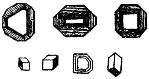
Fig. 78.—Fluosilicate of potassium.[151]
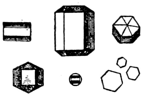
Fig. 79.—Fluosilicate of sodium.[151]
Sodium. From hydrofluosilicic solutions, colorless, very weakly
doubly refracting, hexagonal crystals of Na2SiFl6, which are generally
longer the higher the percentage of sodium in the solution.
This test is very certain even for small amounts.
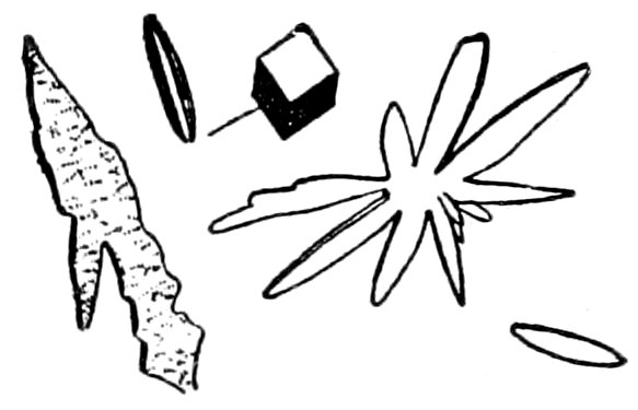
Fig. 80.—Fluosilicate of calcium.[151]

Fig. 81.—Fluosilicate of magnesium.[151]
Calcium. From hydrofluosilicic solutions, monoclinic crystals
of CaSiFl6 + 2H2O of various forms, generally spindle-shaped,
with not very strong double refraction. The crystals have seldom
straight-edged boundaries and are often grouped in rosettes. The
addition of dilute H2SO4 decomposes the crystals, recrystallization
137yielding long prismatic crystals of gypsum (distinction from
strontium).
Treatment with HFl and dilute H2SO4 (in excess), producing on
evaporation characteristic crystals of gypsum, furnishes a very
delicate test for small percentages of calcium.
Magnesium. From hydrofluosilicic solutions, rhombohedral
crystals of MgSiFl6 + 6H2O with plane faces and sharp edges.
The crystals are colorless and strongly doubly refracting with
positive optical character, Fig. 81.
The formation of struvite crystals (NH4MgPO4 + 6H2O), of
coffin-like forms, is very characteristic and takes place from very
dilute solutions (rendered alkaline) on the addition of a grain of
salt of phosphorus or a drop of sodium phosphate.
Iron. From hydrofluosilicic solutions, crystals of FeSiFl6 +
6H2O, which are isomorphous with those of magnesium salts, with
the same optical characters. They may be differentiated by moistening
with potassium ferrocyanide or ammonium sulphide, in
the first case by turning blue, in the second case black.
Aluminium. From hydrofluosilicic solutions, not satisfactory
on account of the gelatinous formation.
When the gelatinous formation is obtained by the action of
hydrofluoric acid on an aluminous silicate, the staining test can be
used to distinguish between fine grains of feldspar and quartz or
iolite and quartz.
Behrens’ Method.[152] (Hydrofluoric and Sulphuric Acids.)
This method depends on common reactions that can be made
rapidly, but has the disadvantage of being rather complicated and
requiring delicate manipulation.
The tests are best made upon about ½ mg. of powder with
HFl (pure and fuming). As soon as the fluorides begin to dry
treat with dilute H2SO4 and warm until white fumes of SO3 appear.
In this way the HFl and SiFl4 are driven off and the sulphates are
left. This part of the test can conveniently be made on a piece
of platinum foil. Add excess of water and concentrate.
138Transfer a drop to a clean object glass and, while still liquid,
examine it with the microscope. Do not use a cover-glass over
the drop.
Crystallizations Obtained by Behrens’ Method.
Potassium. Add a little platinic chloride when octahedral crystals
of K2PtCl6 (size .18 to .30 mm.) will appear, which are clear,
bright yellow in color with strong refraction.
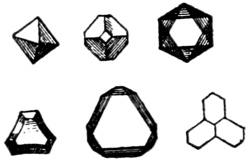
Fig. 82.—Potassium platinic chloride.[153]
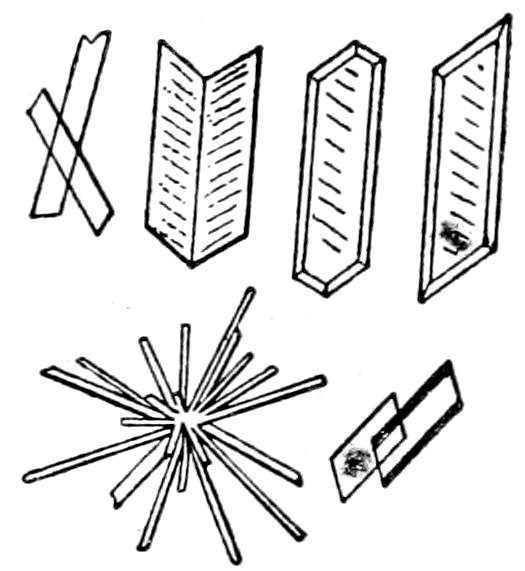
Fig. 83.—Sulphate of calcium (gypsum).[153]
Sodium. Use sulphate of cerium and allow a small amount of
this reagent to act through a capillary pipette upon a drop of the
solution. Very small aggregates of brown crystals (size .02 mm.)
of the double sulphate of cerium and sodium are formed, which
are clearly visible with 600 diams. If potassium is present the
double sulphate of that alkali will appear in larger, grayish grains
(size .05 to .06 mm.). An excess of H2SO4 is to be avoided.
Calcium. After a few minutes little gypsum crystals (CaSO4
+ 2H2O) will appear. In strongly acid solutions the thin acicular
crystals will be grouped in bushes or stars; in neutral solutions
the crystals will have the normal shape of selenite crystals or form
swallow-tailed twins.
Magnesium. Use salt of phosphorus dissolved in water and
allow it to mix with the solution (to which has been added ammonium
chloride and ammonia) through a capillary pipette. From a
solution containing more than 5 per cent. of magnesium are first
deposited X-shaped skeletons and rudimentary crystals of Mg.NH4.PO4
+ 6H2O. If the solution is more dilute beautiful, sharp,
hemimorphic crystals (.10 to .20 mm. in size) of the orthorhombic
139system will appear. These crystals often resemble the roof of
a house. The formation of the crystals is assisted by heat. Iron
and manganese phosphates yield crystals of the same type, but
the iron is separated on the addition of ammonia.
Aluminium. Use chloride of cæsium. Take a drop of the
solution, with excess of H2SO4 driven off, and touch it with a
platinum wire that has been dipped in the melted chloride of
cæsium. Large crystals (.40-.90 mm. in size) of cæsium alum will
form, which are octahedral and cubo-octahedral in shape. Iron
does not interfere, as its crystallization would take place much
more slowly. The solution should not be too concentrated.
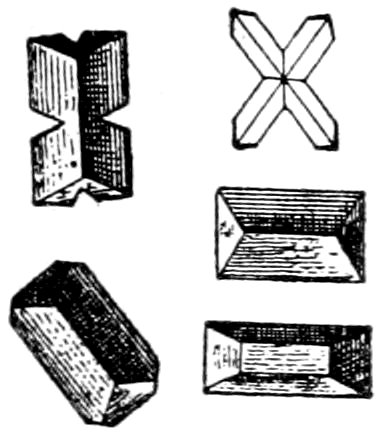
Fig. 84.—Magnesiumammonium phosphate.[154]
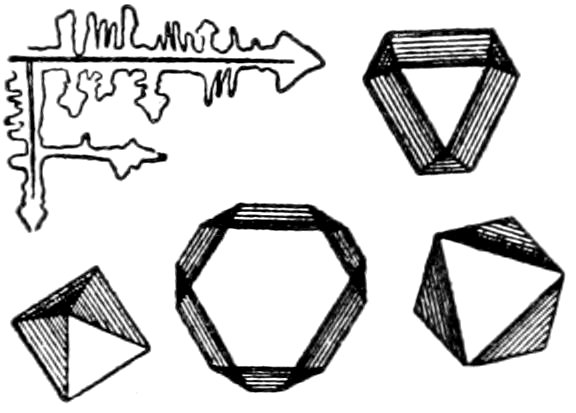
Fig. 85.—Cæsium alum.[154]
Special Tests.
Distinction between haüynite (contains CaSO4) and noselite
(contains Na2SO4). Treat with HCl and on evaporation the characteristic
crystals of gypsum will be seen if the mineral is haüynite.
Dilute acid should be used and as low a temperature maintained
as possible, otherwise crystals of anhydrite would form instead of
gypsum.
Recognition of apatite by test for phosphorus. Treat with a
drop of ammonium molybdate dissolved in HNO3. After complete
action remove the solution to a clean object glass, when after
slight warming a large number of very small yellow crystals
(rhombic dodecahedral in shape) will form. The test may be
140used to distinguish this mineral from nephelite, melilite and natrolite.
In the presence of soluble silica evaporate to render it insoluble
and treat again with HNO3 and the reagent.
Other micro-chemical tests are not mentioned for the reason
that in elaborate chemical investigations of sections or isolated
fragments recourse should be made to the most complete publications
on the subject.
141
APPENDIX.
Brief Scheme of Classification into Systems by Optical Determinations.
- HOMOGENEOUS.
- The whole substance shows the same optical character, except in the case
of twin crystals when the different portions of the twin are affected
differently.
- Isotropic
- All sections of the substance remain dark during a complete rotation
between crossed nicols, and no interference figure is produced
by convergent light.
- Amorphous
- Absence of crystalline form or cleavage.
- Isometric
- Presence of crystalline form or cleavage.
- Anisotropic.
- Sections generally show some interference color and extinguish four times,
at 90° apart, during complete rotation.
- Uniaxial.
- Determined by character of interference figures obtained by convergent
light from sections which remain dark or nearly so during
complete rotation.
-
- All sections show parallel or symmetrical extinction.
- Tetragonal
- Sections giving interference figures are four- or eight-sided, or show
rectangular cleavage.
- Hexagonal
- Sections giving interference figures are three-, six- or nine-sided, or
show cleavage lines intersecting at 60°.
- Biaxial
- Determined by character of interference figures obtained by convergent
light.
- Orthorhombic
- Extinction is parallel or symmetrical in all sections parallel to
ă, [=b] and ć. Color distribution is
symmetrical to two lines and to the central point, see p. 48.
- Monoclinic
- Extinction is only parallel or symmetrical in sections parallel to the
ortho axis [=b]; all other sections show extinction angles. Color
distribution is only symmetrical to one line or to the
central point, see p. 48.
- Triclinic
- Extinction angles in all sections, although in some minerals these angles
may be very small. No symmetry in color distribution, see
p. 48.
- AGGREGATE.
- Not homogeneous, but made up of an aggregation of individuals, all
extinguishing at different times.
142
Double Refraction (maximum).[155]
- 0.287
- Rutile
- 0.179
- Dolomite
- 0.172
- Calcite
- 0.141
- Titanite
- 0.090
- Titanite
- 0.072
- Hornblende (basaltic)
- 0.062
- Zircon
- 0.058
- Biotite
- 0.050
- Talc
- 0.050
- Ægirite
- 0.041
- Muscovite
- 0.037
- Epidote
- 0.036
- Chrysolite (Olivine)
- 0.036
- Scapolite (Meionite)
- 0.034
- Tourmaline
- 0.034
- Phlogopite
- 0.030
- Allanite (Orthite)
- 0.029
- Diopside
- 0.027
- Actinolite
- 0.027
- Tremolite
- 0.024
- Hornblende (common)
- 0.024
- Diallage
- 0.024
- Anthophyllite
- 0.023
- Augite
- 0.021
- Sillimanite (Fibrolite)
- 0.018
- Glaucophane
- 0.017
- Tourmaline (precious)
- 0.016
- Cyanite (Disthene)
- 0.013
- Hypersthene
- 0.013
- Scapolite (Marialite)
- 0.013
- Anorthite
- 0.012
- Natrolite
- 0.011
- Chlorite (Clinochlore)
- 0.011
- Andalusite
- 0.011
- Topaz
- 0.010
- Staurolite
- 0.010
- Gypsum
- 0.010
- Enstatite
- 0.010
- Serpentine
- 0.009
- Corundum
- 0.009
- Iolite (Cordierite)
- 0.009
- Quartz
- 0.008
- Topaz
- 0.008
- Kaolin
- 0.008
- Labradorite, Ab1An1
- 0.008
- Oligoclase, Ab4An1
- 0.008
- Albite
- 0.007
- Orthoclase
- 0.007
- Microcline
- 0.006
- Vesuvianite
- 0.005
- Zoisite
- 0.004
- Nephelite (Elæolite)
- 0.003
- Apatite
- 0.003
- Melilite
- 0.002
- Tridymite
- 0.002
- Leucite
- 0.002
- Allanite (Orthite)
- 0.001
- Chlorite (Penninite)
- 0.001
- Vesuvianite
Indices of Refraction (mean).[155]
- 2.712
- Rutile
- 2.38
- Perofskite
- 2.00
- Spinel (Chrome)
- 1.963
- Titanite
- 1.95
- Zircon
- 1.920
- Titanite
- 1.856
- Garnet (Melanite)
- 1.792
- Ægirite
- 1.78
- Allanite (Orthite)
- 1.78
- Garnet (Almandite)
- 1.766
- Corundum
- 1.751
- Epidote
- 1.75
- Garnet (Pyrope)
- 1.741
- Staurolite
- 1.723
- Hypersthene
- 1.72
- Spinel
- 1.720
- Zoisite
- 1.720
- Cyanite (Disthene)
- 1.719
- Hornblende (basaltic)
- 1.715
- Vesuvianite
- 1.711
- Augite
- 1.699
- Zoisite
- 1.697
- Diopside
- 1.688
- Diallage
- 1.675
- Chrysolite (Olivine)
- 1.665
- Enstatite
- 1.664
- Sillimanite (Fibrolite)
- 1.674
- Tourmaline
- 1.644
- Anthophyllite
- 1.64
- Hornblende (common)
- 1.637
- Andalusite
- 1.635
- Apatite
- 1.632
- Glaucophane
- 1.632
- Topaz
- 1.630
- Melilite
- 1.633
- Tourmaline (precious)
- 1.622
- Dolomite
- 1.621
- Actinolite
- 1.621
- Tremolite
- 1.618
- Biotite
- 1.608
- Topaz
- 1.588
- Chlorite (Clinochlore)
- 1.587
- Muscovite
- 1.582
- Anorthite
- 1.576
- Chlorite (Penninite)
- 1.572
- Talc
- 1.584
- Scapolite (Meionite)
- 1.564
- Phlogopite
- 1.56
- Serpentine
- 1.559
- Labradorite, Ab1An1
- 1.55
- Kaolin
- 1.547
- Quartz
- 1.551
- Scapolite (Marialite)
- 1.601
- Calcite
- 1.541
- Oligoclase, Ab4An1
- 1.54
- + Canada balsam
- 1.539
- Nephelite (Elæolite)
- 1.539
- Iolite (Cordierite)
- 1.535
- Albite
- 1.525
- Gypsum
- 1.525
- Microcline
- 1.523
- Orthoclase
- 1.509
- Leucite
- 1.503
- Haüynite
- 1.488
- Analcite
- 1.483
- Natrolite
- 1.483
- Sodalite
- 1.477
- Tridymite
- 1.46
- Opal
143
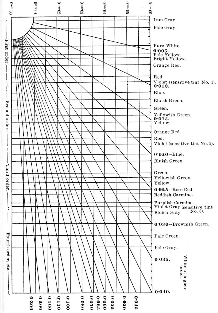
Diagram showing relation between strength of Double Refraction, Interference Colors and Thickness of Section.[156]
144
Order of Consolidation of the Constituent Minerals in Plutonic Rocks.
“There is in plutonic rocks a normal order of consolidation for
the several constituents, which holds good with a high degree of
generality. It is in the main, as pointed out by Rosenbusch, a
law of ‘decreasing basicity.’ The order is briefly as follows:
“1. Minor accessories (apatite, zircon, sphene, garnet, etc.) and
iron ores.
“2. Ferro-magnesian minerals—olivine, rhombic pyroxenes,
augite, ægirine, hornblende, biotite, muscovite.
“3. Felspathic minerals—plagioclase felspars (in order from
anorthite to albite), orthoclase (and anorthoclase).
“4. Quartz, and finally microcline.
“In most rocks such minerals as are present follow the above
order. The most important exceptions are the intergrowth of
orthoclase and quartz and the crystallization of quartz in advance
of orthoclase in some acid rocks, and the rather variable relations
between groups 2 and 3 in some more basic rocks. The order laid
down applies in general to parallel intergrowths of allied minerals;
thus when augite is intergrown with ægirine or hornblende the
former mineral forms the kernel of the complex crystal and the
latter the outer shell; when a plagioclase crystal consists of successive
layers of different compositions the layers become progressively
more acid from the center to the margin.
“Certain constituents having variable relations are omitted from
the foregoing list. Thus nepheline (elæolite) and sodalite belong
to group 3, but may crystallize out either before or after the
feldspar.”[157]
145
OPTICAL SCHEME.
Introduction.
The scheme is designed to furnish the student with a practical method of recognizing the common minerals in rock sections.
The arrangement followed has been to group minerals having
general optical characters in common, at the same time giving
their specific characters so as to make it possible to distinguish
one from another. In each rectangle the minerals are arranged in
order of their indices of refraction.
A tabulation of the minerals, with a list of optical characters
appended, is of aid to the skilled investigator, but of very little
assistance to the beginner.
The more common minerals, or those which are important petrographically,
are printed in heavy-faced type; the minerals of less
importance in small capitals.
Abbreviations and Conventions Used.
A. = Amorphous.
I. = Isometric system.
T. = Tetragonal system.
O. = Orthorhombic system.
M. = Monoclinic system.
Tri. = Triclinic system.
H. = Hexagonal system.
M(H). = Monoclinic, with hexagonal form or characters, as in the case of
biotite.
⟂ = At right angles to.
El. = Elongation.
Ex. = Extinction.
∥ Ex. = Parallel extinction, as when the crystals extinguish parallel to cleavage
lines or crystal edges. Extinction which is symmetrical to intersecting
cleavage lines is also included under this term.
The mean refractive indices are printed in heavy-faced type.
The term “grains” is used to describe not only minerals which occur in
typically granular form, but also those which have coarser allotriomorphic form,
as elæolite and sodalite in plutonic rocks, such as syenite, etc.
146
General Rules for Use of Scheme.
The division of the scheme into two vertical columns is based
on the values of the mean refractive indices, as determined by the
“relief” and appearance of the surface. When the refractive index
is above 1.60, the relief is fairly well to distinctly marked and the
surface rough to very rough, depending on the value of the index.
Most of the rock-forming minerals with indices below 1.60 show
no relief and a smooth surface, except in the case of a few of the
rarer minerals (mostly isometric), which have very low indices
and hence rough surface.
Mistakes may easily be made in the case of minerals near the
limit; but practice and the use of the Becke test should soon make
possible the classification into the two groups suggested by the
scheme, and the appended descriptions will help to check errors.
When an unknown mineral lies adjacent to one that is known,
use the Becke test for obtaining the relative refractive index of the
unknown mineral; focus sharply on the line of contact between
the known and unknown minerals,[158] then raise the objective slightly
and the “bright line” will appear on the side of the mineral having
the higher index. The method of Schrœder van der Kolk may
also be employed, see p. 22.
The horizontal divisions of the scheme depend on the relative
strength of the double refraction based on the observed interference
colors. These colors to be of use in classification must be
correctly recognized. The lower and middle colors of the 1°
order, from bluish-gray through white to yellow, are easily known.
The bright red, blue, green, etc., colors of the 1°, 2° and 3° orders
can also be differentiated without trouble from the very high
order colors (4° and above), which are essentially white in tone
with no decided color tint.
When confusion arises, the exact order of the color can be
determined by a quartz wedge, as given on p. 35. Furthermore,
a ¼ undulation mica plate serves to quickly distinguish between
the 1° order white and the practically colorless, high order tint of
calcite, titanite, etc.; as after the insertion of the test-plate the 1°
order white suffers a marked change in color, while the very high
order (practically white) tint shows no appreciable change.
147In the determination of these interference colors care must be
given to considerations of orientation and thickness. The section
must give the maximum interference color of all the obtainable
sections of the mineral in the rock section. Such sections will be
parallel to the ć axis in the uniaxial minerals and to the axial plane
in the biaxial minerals; and will, therefore, in convergent light
never show the emergence of an optic axis or bisectrix. Crystal
“form,” cleavage, pleochroism, etc., may at times aid in the selection
of these sections. The thickness of the section must also be
considered, and it is well in all cases to pick out some known
mineral in the section, as quartz, and note its maximum interference
color. Knowing how this varies from the color given by the
scheme for a section 0.03 mm.[159] in thickness, due allowance can
be made for a like variation in the colors given by the other minerals.
In the case of minerals with strong absorption the interference
colors may not be noticeable on account of the absorption
of parts of the light.
Under the subhead of pleochroism, the vibration direction of the
ray of a definite color is given and not the direction of transmission
of that ray.
The interference figures in convergent light increase in clearness
and distinctness with the strength of the double refraction.
In uniaxial crystals sections at right angles to the optic axis, i. e.,
sections which remain dark during a revolution between crossed
nicols, show the best interference figures. In biaxial crystals the
most characteristic interference figures are shown by sections at
right angles to the acute bisectrix.
Crystal sections which are too small do not give very satisfactory
interference figures with convergent light.[160]
Any scheme, however designed, makes a more or less arbitrary
classification of the minerals, and when in doubt it is always safer
to look for the mineral on both sides of the scheme line.
The rarer minerals are not included in this scheme, so when the
determination of a mineral is uncertain or not positive recourse
should be had to more elaborate tables.
149
INDEX.
MINERAL NAMES IN HEAVY-FACED TYPE.
- Abbreviations, ix
- Abnormal interference colors, 30
- Absorption, 26
- Acmite, 83
- Actinolite, 84
- Acute bisectrix, 5
- Ægirine, 83
- Ægirine-augite, 84
- Aggregate structure, 38
- Albite, 103
- Allanite, 96
- Allotriomorphic, 15
- Aluminium, test for, by Borichy’s method, 137
- test for, by Behren’s method, 139
- Amorphous bodies, 2
- Amorphous substances, test for, 26
- Amphibole, 84
- Analcite, 56
- Analyzer, 10
- Andalusite, 72
- Anhedron, 15
- Anisotropic character, test for, 27
- Anisotropic crystals, 2
- Anomalies, optical, 27
- Anorthite, 103
- Anorthoclase, 113
- Anthophyllite, 88
- Antigorite, 114
- Apatite, 68
- Apatite, recognition of, by test for phosphorus, 139
- Apparatus for petrographical laboratory, 127
- Appendix, 141
- Arfvedsonite, 88
- Augite, 80
- Automorphic, 13
- Axes of elasticity, 4
- Axial angle, 5
- Axial plane, 5
- Basaltic Hornblende, 85
- Bastite, 77
- Becke’s method for determining relative values of refractive indices, 19
- Behren’s method. (Hydrofluoric and sulphuric acids), 137
- Bertrand lens, 11
- Biaxial crystals, 4, 5
- vibration directions in, 4
- Biaxial interference figures, 43
- Biotite, 89
- Bisectrix, acute, 5
- Borichy’s method. (Hydrofluosilicic acid), 135
- Broken or strained crystals, 15
- Bronzite, 76
- Calcite, 65
- Calcium, test for, by Borichy’s method, 136
- test for, by Behren’s method, 138
- “Cap” nicol, 10
- Carbonaceous Matter, 61
- Carbonaceous particles, test for, 132
- Carbonates, test for, 130
- Cement, 122
- Cementing, 121
- Centering stage, 10
- Chalcedony, 64
- Characters observed by, convergent light, 40
- crossed nicols, 26
- reflected light, 13
- polarized light, 25
- Characters of opaque minerals, 13
- Chemical and mechanical tests, 129
- Chemical (micro) reactions, 134
- separation, 134
- tests on crystal in section, 129
- Chiastolite, 72
- Chlorite group, 92
- Chromite, 52
- 150Chrysolite, 77
- Chrysotile, 114
- Circular polarization, 3
- Classification into systems by optical determinations, 141
- Clay, 115
- Cleaning and finishing sections, 126
- Cleaning microscope, 11
- Cleavage, 23
- Clinozoisite, 96
- Color, 17
- diagram (interference), 143
- fringes, 48
- Condensing lens, 9
- Consolidation of minerals in plutonic rocks, order of, 144
- Conventions, ix
- Convergent light, 40
- characters observed by, 40
- Convergent and parallel light, résumé of uses of, 49
- Cordierite, 78
- Corroded crystals, 15
- Corundum, 62
- Crossed nicols, characters observed by, 26
- Crossed twinning, 37
- Crystallites, 16
- Crystallizations obtained by Behren’s method, 137
- Crystals bounded by planes, 13
- Crystals without bounding planes, 15
- Cutting, 120
- Cutting and grinding machines, 117
- Cyanite, 113
- Damourite, 92
- Delessite, 94
- Diagram, showing relation between strength of double refraction, interference colors and thickness of section, 143
- Diallage, 80
- Diamond saws, 119
- Dichroite, 78
- Diopside, 80
- Dipyre, 59
- Directions of elasticity, ix
- Dispersion, 5, 48
- Disthene, 113
- Dolomite, 67
- Double image, 2
- Double refraction, 2, 27
- estimation of strength of, 30
- strength of, measured by von Federow mica wedge, 35
- table (maximum), 142
- Effects produced by crystals on transmitted light, 2
- Elæolite, 69
- Elasticity, axes of, 4
- Electric motor for grinding machines, 117
- Electro-magnetic separation, 134
- Emery, grades of, for grinding, 124
- Enstatite, 75
- Epidote, 94
- Etched figures, 130
- Extinction, 31
- angles, 5, 31
- tests for, 32
- wavy, 31
- Extraordinary ray, 3
- Eye-pieces, 11
- Faster and slower rays, test for vibration directions of, 33
- Fayalite, 78
- Feldspar Group, 98
- Feldspathoids, 69
- Fibrolite, 73
- Finishing and cleaning sections, 126
- Focusing, 11
- Form of crystals, 13
- Fracture, 24
- Garnet, 53
- Gelatinizing silica, test for, 130
- Glass slides, 125
- Glaucophane, 88
- Graphite, 61
- Gravity (specific) separation, 133
- Gridiron twinning, 37
- Grinding, 123
- Grinding and cutting machines, 117
- apparatus for sections with parallel faces, 118
- plates or laps, 121
- Gypsum, 80
- Gypsum test-plate, 33
- 151Hardness of grains, 132
- Haüyne, 56
- Haüynite, 56
- Haüynite and noselite, micro-chemical distinction between, 139
- Heating sections to redness, 131
- Heavy solutions, 133
- Hematite, 61
- Hexagonal crystals, 4
- High relief, 17
- Hornblende, 84
- Hyalosiderite, 78
- Hydrargillite, 115
- Hydrofluosilicic acid test, 135
- Hypersthene, 75
- Idiomorphic, 13
- Idocrase, 60
- Ilmenite, 62
- Inclusions, 24
- Index of refraction, ix, 17
- by Becke’s method, 19
- by Schrœder van der Kolk’s method, 22
- by Sorby’s method, 19
- Indicators for specific gravity separation, 133
- Indices of refraction (mean), table of, 142
- Interference color, determination of order of, 35
- Interference colors, 28
- Interference colors (abnormal), 30
- Interference figures, 40
- Investigation of microscopic and optical characters of minerals, 13
- Iolite, 78
- Iron, test for, by Borichy’s method, 137
- test for, by Behren’s method, 139
- Isolating crystals or mineral fragments for testing, 132
- Isometric crystals, 2
- Isotropic character, 26, 40
- Kaolin, 115
- Labradorite, 103
- Laps for grinding, 121
- Leucite, 54
- Leucoxene, 62
- Light, ordinary, 1
- Limonite, 51
- Lithia Mica, 92
- Machines for cutting and grinding, 117
- Magnesium, test for, by Borichy’s method, 137
- test for, by Behren’s method, 138
- Magnetic iron ore, 52
- Magnetic pyrites, 51
- Magnetite, 52
- Measuring strength of double refraction by von Federow mica wedge, 35
- Mechanical and chemical tests, 129
- Melilite, 61
- Menaccanite, 62
- Methods of preparing sections, 117
- Mica Group, 89
- Mica plate (quarter undulation), 33
- Mica wedge, von Federow, 35
- Micro-chemical reactions, 134
- Microcline, 102
- Microlites, 17
- Microscope (petrographical), 7
- Microscopic and optical characters of minerals, 51
- Minerals and thickness of section, determined by table and diagram, 36
- Monoclinic crystals, 4
- principal vibration directions in, 5
- Monoclinic pyroxenes, 80
- Mounting sections, 124
- Muscovite, 89
- Natrolite, 79
- Negative optical character, biaxial, 46
- Nepheline, 69
- Nephelite, 69
- Nicol prism, 7
- Nosean, 56
- Noselite, 56
- Noselite and haüynite, micro-chemical distinction between, 139
- Nose-piece for microscope, 10
- Objectives, 10
- 152Oblique extinction, 31
- Obtuse bisectrix, 5
- Oligoclase, 103
- Olivine, 77
- Opal, 51
- Opaque minerals, characters of, 13
- Optical, anomalies, 27
- character, biaxial, 46
- character, uniaxial, 42
- classification into systems, 141
- distinctions between orthorhombic, monoclinic and triclinic sections (perpendicular to bisectrices), 48, 141
- distinctions between tetragonal and hexagonal sections (perpendicular to optic axis), 141
- and microscopic characters of minerals, 51
- principal section, 3, 4
- scheme, 145
- Optic axes, 4
- Optic axis, 3
- Optics for optical mineralogy, 1
- Order of consolidation of minerals in plutonic rocks, 144
- Order of interference color, determination of, 35
- Ordinary light, 1
- Orthite, 96
- Orthoclase, 98
- Orthorhombic crystals, 4
- principal vibration directions in, 4
- Orthorhombic pyroxenes, 75
- Parallel and convergent light, résumé of uses of, 49
- Parallel extinction, 31
- Parallel face sections, grinding apparatus for, 119
- Pargasite, 85
- Perofskite, 57
- Perovskite, 57
- Petrographical apparatus, 127
- Petrographical microscope, 7
- Phenocryst, 14
- Phlogopite, 89
- Picotite, 53
- Piedmontite, 95
- Plagioclases, 103
- Plane polarized light, 1
- Plates, grinding, 121
- Pleochroic halos, 59
- Pleochroism, 25
- Pleonaste, 53
- Polarization colors, 28
- Polarized light, characters observed by, 25
- Polarizer, 7
- test for vibration plane of, 9
- Polishing sections, 124
- Polysynthetic twinning, 37
- Positive optical character, biaxial, 46
- Potassium, test for, by Borichy’s method, 136
- test for, by Behren’s method, 138
- Preparation of sections, 117
- Principal section, optical, 3, 4
- Principal vibration directions, 3, 4
- Prism, nicol, 7
- Pseudomorphic structure, 39
- Pyrite, 51
- Pyrites, 51
- Pyroxenes, monoclinic, 80
- Pyroxenes, orthorhombic, 75
- Pyrrhotite, 51
- Quarter-undulation mica plate, 33
- Quartz, 63
- Reflected light, characters observed by, 13
- Reflector, 7
- Refraction, double, 2, 27
- Refraction, index of, ix, 17
- Refractive indices (mean), table of, 142
- Relief, 17
- Resorption border, 15
- Résumé of uses of parallel and convergent light, 49
- Rotating stage of microscope, 10
- Rutile, 57
- Sagenite, 58
- Sanidine, 102
- Saussurite, 96, 113
- 153Saws, 119
- Scapolite Group, 59
- Scheme of classification into systems by optical determinations, 141
- Scheme, optical, 145
- Schiller structure, 25
- Schrœder van der Kolk’s method for determining refractive indices, 22
- Sections, methods of preparing, 117
- Selenite plate, 33
- Separation, by chemical means, 134
- by electro-magnet, 134
- by specific gravity, 133
- Sericite, 92
- Serpentine, 114
- Shagreened surface, 17
- Shorl, 70
- Sillimanite, 73
- Simple twinning, 37
- Single image, 2
- Skeleton forms, 17
- Slides, glass, 125
- Slower and faster rays, test for vibration directions of, 33
- Sodalite, 56
- Sodalite Group, 56
- Sodium, test for, by Borichy’s method, 136
- test for, by Behren’s method, 138
- Sorby’s method for determining index of refraction, 19
- Special micro-chemical tests, 139
- Specific gravity separation, indicators for, 133
- Sphærulitic structure, 39
- Sphene, 96
- Spinel, 53
- Stage of microscope, rotating, 10
- Staurolite, 74
- Strained or broken crystals, 15
- Strength of double refraction, measure of, 30, 35
- Structure, 37
- Symmetrical extinction, 31
- Systems, classification into, by optical determinations, 141
- Table, double refraction, 142
- Table, indices of refraction, 142
- Talc, 94
- Test for vibration plane of polarizer, 9
- Tetragonal crystals, 4
- Thickness of rock sections, 124
- Thickness of section and minerals, determined by table and diagram, 36
- Titanite, 96
- Transmitted light, characters observed by, 13
- Transparent minerals, investigation of characters of, 13
- Tremolite, 84
- Triclinic crystals, 4
- principal vibration directions in, 5
- Tridymite, 65
- Topaz, 74
- Tourmaline, 70
- Twinning, 37
- Uniaxial crystals, vibration directions in, 3
- Uniaxial interference figures, 40
- Uralite, 88
- Uralitization, 88
- Uses of parallel and convergent light, 49
- van der Kolk’s, Schrœder, method for determining refractive indices, 22
- Vesuvianite, 60
- Vibration direction, 2
- directions of faster and slower rays, test for, 33
- directions, principal, 3, 4
- plane of nicol, 9
- plane of polarizer, test for, 9
- von Federow mica wedge, 35
- Wavy extinction, 16, 31
- Wedge, mica, 35
- Wernerite, 59
- Xenomorphic, 15
- Zeolites, 79
- Zircon, 58
- Zoisite, 96
- Zonal structure, 38
P. 33, line 23, for beat read be at.
P. 66, line 10, after appearance add (sometimes called “twinkling”).
Corrections for mean index of refraction n′: p. 60, line 1, 1.551
to 1.584; p. 62, line 29, 1.766; p. 66, line 3, 1.601; p. 67, line 24,
1.622; p. 71, line 10, 1.633 to 1.674.
Corrections for Indices of Refraction (mean) in Table on p.
142: Corundum 1.766; Tourmaline 1.674; Tourmaline (precious)
1.633; Dolomite 1.622; Scapolite (Meionite) 1.584; Scapolite
(Marialite) 1.551; Calcite 1.601.
Corrections for mean indices of refraction in Scheme (insert
folder): Scapolite 1.551 to 1.584; Calcite 1.601 and transfer to
Dolomite rectangle; Dolomite 1.622; Corundum 1.766; Tourmaline
1.633 to 1.674.
| Page |
Changed from |
Changed to |
| 80 |
occurs as an alternation product of anhydrite. Gypsum is soluble in hydrochloric |
occurs as an alteration product of anhydrite. Gypsum is soluble in hydrochloric |
| 136 |
longer the higher the percentage of calcium in the solution |
longer the higher the percentage of sodium in the solution |
- Typos fixed; non-standard spelling and dialect retained.
- The author used the old chemical symbol (Fl) for Fluorine.
- Corrected the Errata with the exception of the last paragraph "Corrections
for mean indices of refraction in Scheme (insert folder)" .
- Used numbers for footnotes, placing them all at the end of the last chapter.
![[Logo]](images/titlepage.jpg)